Operating instructions i550 cabinet frequency inverter | 16
© 11/2021 · EN · www.Lenze.com
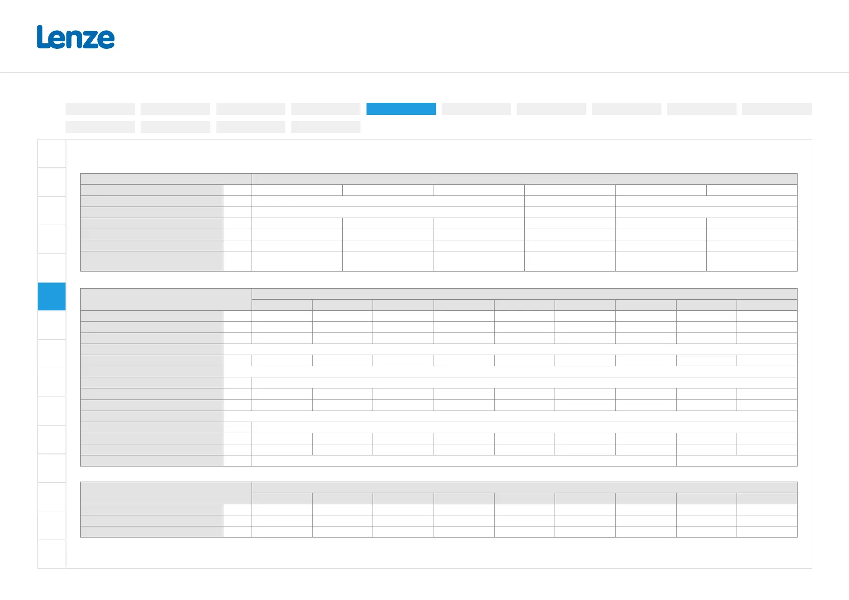
3-phase mains connection 230/240V (195 V ... 264 V, 45 Hz ... 65 Hz)
Terminal data
Inverter I55AExxxD (1/3-phase), I55AExxxC (3-phase)
Rated power kW 0.25 ... 0.75 1.1 ... 2.2 4 ...5.5 0.25 ... 5.5 0.25 ... 2.2 4 ... 5.5
Connection Mains connection X100 PE connection Motor connection X105
Connection type Screw terminal Screw Screw terminal
Max. cable cross-section mm² 2.5 6 6 6 2.5 6
Stripping length mm 8 8 9 10 8 9
Tightening torque Nm 0.5 0.7 0.5 2 0.5 0.5
Required tool
0.5 x 3.0
0.6 x 3.5
0.6 x 3.5
TX20
0.5 x 3.0
0.6 x 3.5
Rated data (Heavy Duty) und fusing data
Inverter
I55AE
125D 137D 155D 175D 211D 215D 222D 240C 255C
Rated power kW 0.25 0.37 0.55 0.75 1.1 1.5 2.2 4 5.5
Rated output current (8 kHz) A 1.7 2.4 3.2 4.2 6 7 9.6 16.5 23
Max. output current * A 3.4 4.8 6.4 8.4 12 14 19.2 33 46
Operation without mains choke
Rated mains current A 2.6 3.9 4.8 6.4 7.8 9.5 13.6 20.6 28.8
Fuse
Characteristic gG/gL or gRL
Max. rated current A 16 16 16 16 32 32 32 40 40
Max. short circuit current (SCCR) kA 65 65 65 65 65 65 65 65 65
Circuit breaker
Characteristic B, C
Max. rated current A 16 16 16 16 32 32 32 40 40
Max. short circuit current (SCCR) kA 65 65 65 65 65 65 65 65 65
Residual current device (RCD) ≥ 30 mA, type B ≥ 300 mA, type B
Rated data (light duty)
Inverter
I55AE
125D 137D 155D 175D 211D 215D 222D 240C 255C
Rated power kW - - - - - - - 5.5 7.5
Rated output current (4 kHz) A - - - - - - - 20.6 27.6
Max. output current * A - - - - - - - 33 46
* Overload time = 3s, recovery time = 12s
Electrical installation
3-phase | 480 V
3-phase | 230/240V
3-phase | 400 V1-phase | 120V
1-phase | 230/240V
Control terminals
Relay output
Connection diagram
Brake resistor
Networks
Functional safety
Safe torque o (STO)
PTC input
Preparation
 Loading...


