Operating instructions i550 cabinet frequency inverter | 25
© 11/2021 · EN · www.Lenze.com
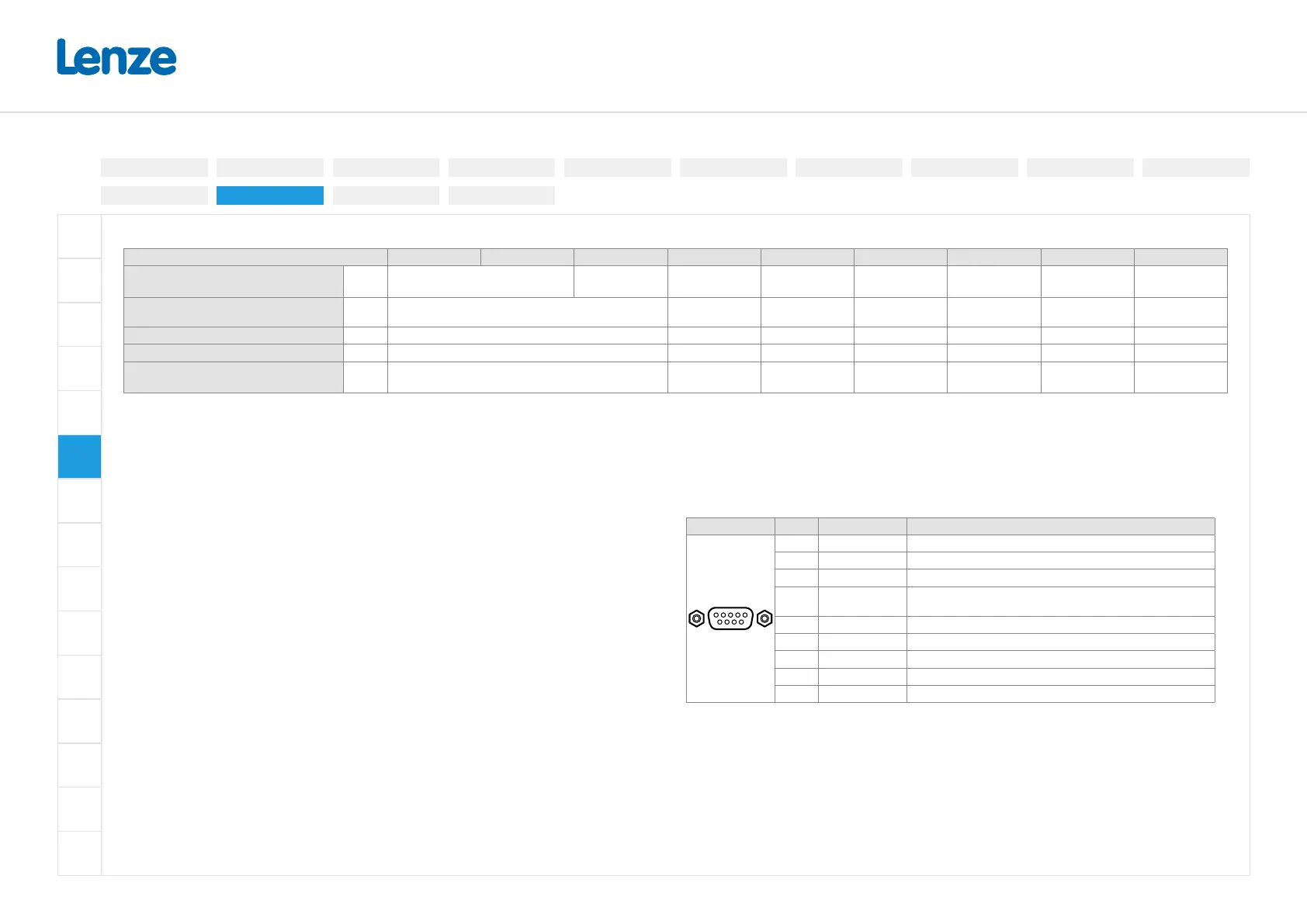
Networks
Network CANopen Modbus RTU IO-Link PROFIBUS EtherCAT EtherNet/IP Modbus TCP POWERLINK PROFINET
Connection X216 X316 X226
X246
X247
X266
X267
X276
X277
X286
X287
X256
X257
Connection type Spring terminal, pluggable
Sub-D socket,
9-pole
RJ45 RJ45 RJ45 RJ45 RJ45
Max. cable cross-section mm² 2.5 - - - - - -
Stripping length mm 10 - - - - - -
Required tool
0.4 x 2.5
- - - - - -
CANopen / Modbus RTU
The network must be terminated with a resistor at the rst and last physical node. At these
nodes, set the DIP switch "R" to ON.
You can use the other DIP switches to set the node address and baud rate. When these DIP
switches are all in the OFF position: Node address = setting in P510.01, baud rate = setting
in P510.02. For Modbus RTU, the baud rate and parity are detected automatically in OFF
position.
EtherCAT
You can set the EtherCAT identier for “Explicit Device Identication” using the rotary encoder
switches. When both are in position 0: Identier = setting in P510.04.
Ethernet/IP / Modbus TCP
You can set the last byte of the IP address using the rotary encoder switches:
192.168.124.<switch position>. When both are in position 0: IP address = setting in P510.01.
POWERLINK
The rotary encoder switches allow you to set the node address (last byte of the IP address).
Resulting IP address: 192.168.100.<switch position> When both are in position 0: Node
address = setting in 0x23C1:004.
PROFIBUS
The network must be terminated with a resistor at the rst and last physical node. Activate the
bus terminating resistor in the bus connector at these nodes.
Use the DIP switches to set the station address. When all DIP switches are in OFF position:
Station address = setting in P510.01, the baude rate is detected automatically.
X226 Pin Assignment Description
1
6
5
9
1 Shield Additional shield connection
2 n. c.
3 RxD/TxD-P Data line-B (received data/transmitted data +)
4 RTS
Request To Send (received data/transmitted data, no
dierential signal)
5 M5V2 Reference potential (bus terminating resistor -)
6 P5V2 5 V DC / 30 mA (bus terminating resistor +, OLM, OLP)
7 n. c.
8 RxD/TxD-N Data line-A (received data/transmitted data -)
9 n. c.
PROFINET
The rotary encoder switches have no function.
Electrical installation
3-phase | 480 V
3-phase | 230/240V
3-phase | 400 V1-phase | 120V
1-phase | 230/240V
Control terminals
Relay output
Connection diagram
Brake resistor
Networks
Functional safety
Safe torque o (STO)
PTC input
Preparation
 Loading...


