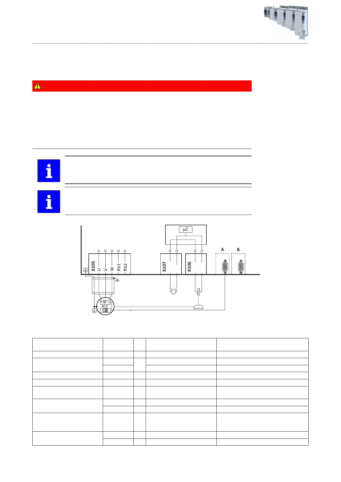
Motor holding brake c
onnecon
The inverter is designed for 24 V brakes. A motor holding brake is connected to X106 and
supplied via X107.
DANGER!
Loss of the safe isolaon
Sa
fe isolaon of the control card from the mains potenal is deacvated when the motor and
motor holding brake are connected via a system cable AND X5 and X107 are supplied by a
common power supply unit. This also applies when using a SELV/PELV power supply unit.
Possible consequences: Electric shock in the event of a fault.
▶
Supply X107 and X5 by separate SELV/PELV power supply units if the motor and motor
holding brake are connected via a system cable.
X107 and X5 can be supplied by a common SELV/PELV power supply unit if the
mot
or and motor holding brake are connected via safely isolated installed
cables.
When the motor holding brake is open, a slight knocking sound can be noced
in the mot
or. This stems from test pulses for monitoring the motor brake
control.
n
EYF
GB
24B
DC 24 V SELV/PELV
(+19.2 V ... +28.8 V)
BD2
BD1
Fig. 12: Connecon diagr
am - motor holding brake
Motor holding brake c
onnecon
Terminal X106: temperature connecon T1 /
T2 BD1, BD2
Controlling a motor holding brake with or
without brake voltage reducon
Level V LOW: < +5, HIGH: > +15
Max. Output current 0.37 ... 15 kW A 2.5
22 ... 110 kW 5.0
Cycle me ms 1
Short-circuit-proof Unlimited period
Suppressor circuit Integrated freewheeling diode and
spark suppressor
Max. Breaking energy 0.37 ... 15 kW Ws 5
22 ... 110 kW Ws 20
Max. Switching rate 6/min. at max. output current Depending on the output current:
Switching frequency doubles if the output
current is halved
Insulaon Basic insulaon Connecon via s
ystem cable
Double/reinforced insulaon Connecon via separated cable
Electrical ins
tallaon
Motor holding brake connecon
152
 Loading...


