Do you have a question about the Leroy-Somer DIGIDRIVE Series and is the answer not in the manual?
Explains the DIGIDRIVE's open loop flux vector control for induction motors.
Lists input/output electrical specs, including current, power, and frequency ranges.
Details regulation modes, control logic, operation modes, and output features.
Specifies operating temperature, storage, humidity, vibration, and EMC standards.
Provides physical dimensions and weight data for different drive ratings.
Outlines checks to perform after receiving the drive to ensure it's undamaged.
Provides guidelines for optimal drive mounting and spacing for ventilation.
Details the procedure for physically mounting the DIGIDRIVE unit.
Specifies requirements for UL standard compliance, including enclosure types.
Explains how to open the drive to access the terminal blocks for wiring.
Shows the physical arrangement of power and control terminal blocks.
Details the function of each terminal on the power and control blocks.
Specifies cable cross-sections, fuse types, and protective devices.
Discusses harmonics, RFI, and EMC considerations for proper operation.
Provides schematic diagrams for single-phase and three-phase power and control circuits.
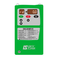
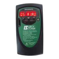
Explains the functions of the control panel buttons and display segments.
Details how to interpret various status messages shown on the drive display.
Outlines the structure for accessing and modifying drive parameters via the keypad.
Guides on how to configure the drive for negative logic control inputs.
Explains the procedure for restoring default factory parameter settings.
Details how to set up and manage a security code to protect parameters.
Step-by-step guide for initial drive setup and motor parameter configuration.
Information on accessing and configuring advanced parameters beyond level 1.
Lists factory settings specific to 60Hz power supplies.
Describes the setup for a specific configuration involving brake control.
Lists error codes, their reasons, points to check, and solutions.
Explains informational alarms that warn the user without necessarily stopping the drive.
Details internal drive faults indicated by HFxx error codes.
General safety precautions and warnings before performing maintenance.
Guidelines for handling and cleaning the drive to prevent issues.
Describes methods for measuring electrical parameters of the drive.
Information on how to obtain spare parts for the DIGIDRIVE.
Procedures and cautions for returning or exchanging the drive.
Details on Type 1 filters used to reduce electromagnetic emissions.
Details on Type 2 filters for reducing electromagnetic emissions.
Information on selecting and installing RF braking resistors for specific ratings.
Explains the use of the FLASHKEY for copying parameter sets between drives.
Describes MC chokes for attenuating earth leakage currents on the drive output.
Information on connecting and using the serial link for drive communication.
Details on the PM10V option for bi-directional analogue control and relay output.
Information on line chokes for attenuating mains supply interference.
Guide for setting up and using the Modbus RTU communication protocol.
Overview of available fieldbus options for integrating the drive into networks.
Mentions extended functionalities available via UNIPAD console and DIGISOFT software.
| Control Mode | Vector control, V/f control |
|---|---|
| Protection | Overcurrent, overvoltage, undervoltage, overload, short circuit |
| Communication | Modbus, CANopen, Profibus |
| Enclosure | IP20, IP21, IP54 (depending on model) |
| Cooling Method | Forced air cooling |
| Humidity | 5% to 95% non-condensing |
| Altitude | Up to 1000m |