Do you have a question about the Leroy-Somer FMV 2307 and is the answer not in the manual?
Important safety notices regarding electrical and mechanical interventions on the inverter.
Explains the relationship between motor speed, poles, and power supply frequency.
Illustrates the internal structure and signal flow of the FMV 2107 and FMV 2307 inverters.
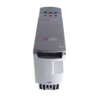
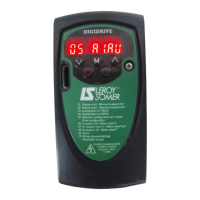
Details the naming convention for FMV 2107 and FMV 2307 inverter models.
Provides key electrical specifications for FMV 2107 and FMV 2307 inverters.
Details various operational characteristics, regulation modes, and control functions.
Lists potential faults, their causes, and recommended solutions for inverter operation.
Specifies operating temperature, humidity, vibration, and immunity standards.
Provides guidance on heat dissipation and cubicle installation requirements.
Lists the weights for different FMV 2107 and FMV 2307 inverter models.
Presents the overall physical dimensions of the inverters.
Instructions for verifying the inverter upon delivery and checking accessories.
Safety and environmental guidelines for installing the inverter.
General information and specific methods for mounting the inverter.
Details on DIN rail mounting, frame mounting, and through-panel mounting procedures.
Diagrams and descriptions for connecting power supply and motor to the inverter.
Specifies motor connection types (Delta or Y) for different inverter models.
Details on connecting control signals, references, and digital inputs/outputs.
Introduces the two main phenomena associated with frequency inverters.
Explains low frequency harmonic feedback on the power supply.
Discusses the emission of radio frequency signals and potential interference.
Details relevant European standards for harmonic emissions and RFI.
Guidelines for proper earthing connections and cable routing.
Recommendations for routing power and signal cables within enclosures.
Advice on external wiring, including chokes for long motor cables.
Steps to solve interference problems in domestic and industrial settings.
Specifies cable cross-sections and fuse ratings for inverter protection.
Covers parallel motor connections, bypass operation, and contactor control.
Details motor contactor stop, earth connections, and parallel DC bus connections.
Introduction to serial link communication using RS 485/RS 422 standards.
Wiring diagrams and specifications for RS 485 and RS 422 serial links.
Details on configuring serial address, baud rate, and access levels.
Wiring diagram for controlling the inverter using the operator panel.
Wiring diagram for terminal block control with stop and jog functions.
Wiring for terminal block control with preset speeds and brake.
Wiring for terminal block control with speed adjustment and direction changes.
Overview of the operator panel display, keys, and parameter organization.
Explanation of parameter types and how to access and modify them.
Detailed procedures for modifying parameters, setting security codes, and reading fault logs.
Steps for setting up the inverter using the operator panel.
Steps for setting up the inverter using terminal block connections.
Using terminal C4 for torque control or limitation.
Using terminal C9 to fix or release the motor speed.
Instructions for using the PI loop for regulation with external sensors.
Comprehensive table of main parameters, their settings, and factory defaults.
Details on specific parameters for skip frequencies, preset speeds, and ramps.
Detailed explanations of key parameters like output frequency, ramps, and overload.
Guide to configuring basic inverter functions like commands, frequency, and torque.
How to select run, reverse, and stop commands via various control methods.
Methods for adjusting output frequency and motor torque.
Configuration options for stopping the motor in case of faults.
Configuration of acceleration time and torque, including BOOST.
Settings for operating frequencies, speeds, and slip compensation.
How to display inverter frequency, load, and fault information.
Tips for improving motor protection, torque limitation, and drive quality.
Selection of different motor stopping modes like ramp, freewheel, and DC injection.
Methods for selecting run, reverse, and stop commands.
Configuration of operating frequency range and regulation mode (torque/frequency).
Fault handling and automatic restart settings.
Control initiation commands and acceleration torque adjustments.
Settings for operating frequencies, preset speeds, and inching.
Selection of display type for analogue and logic signals.
Adjusting switching frequency and prohibiting critical frequencies.
Settings for overload current, continuous current, and torque limitation.
Adjusting slip compensation for improved motor speed regulation.
Selection of stopping modes and ramp adjustments.
Control of an electro-mechanical brake using logic output or relay.
Lists error messages, their reasons, check points, and solutions.
Describes inverter status indications like 'rdY', 'XXX', 'dc', 'Inh', and 'SCN'.
Explains how logic outputs (A1, A2, A3, B1) indicate inverter status or parameters.
Diagnostic flowcharts to help troubleshoot inverter and motor issues.
General safety precautions and maintenance overview for the inverter.
Guidelines for cleaning, protecting, and maintaining the inverter's components.
Methods for measuring electrical values at the inverter's output and input.
Procedures for testing the inverter's power stages for faults.
Tests to verify the inverter's isolation and withstand voltage capabilities.
Information on obtaining spare parts and procedures for product exchange.
Details on R-FMV braking resistances, their characteristics and dimensions.
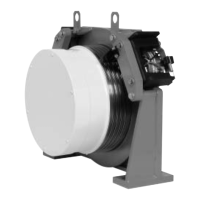
Information on L-FMV lifting interfaces for FMV 2307T, including operation and dimensions.
Description of RFI filters and motor chokes for reducing interference.
Information on the PEGASE software for inverter parameter configuration.
| Brand | Leroy-Somer |
|---|---|
| Model | FMV 2307 |
| Category | DC Drives |
| Language | English |