In operation
•
Very high transmission rate (max. 400
μ
s per telegram)
•
Reliable transmission due to ample performance reserve
•
Insensitive to interference
•
Insensitive to outside light
•
Multiple transmission repeats
•
Storage of output signals
•
Adjustable transmit and receive addresses
3.3 Structure
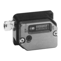
Housing The data transmission unit DLSP is accommodated in a durable housing. Each unit
comprises a transmitter and receiver. The housing is protected against the effects
of splash water (IP 65).
Displays There are 18 LEDs located on the front of the unit which indicate the operating
status of the DLSP, as well as signals to the inputs and outputs.
Setting The range can be set by altering the sensitivity of the receiver at a potentiometer.
Installation The connection unit AT 160xx is prepared for screw mounting onto panels or
brackets (dimensional drawing: see Specifications).
Connection Depending on the configuration of the connection unit, the DLSP is connected by
means of solder terminals, spring-type terminals or ribbon cable with crimp-type
connection. Cable feed-in is either at the side or through the rear wall by means of
a cable gland.
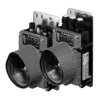
Fig. 2 DLSP structure
1 Electronic and display unit DLSP 160S
2 Sensitivity setting
3 Transmit/receive window
4 Input/output status displays
5 Connection unit AT 160xx (mounting, connection)
6 Cable gland (rear wall)
7 Cable gland (side)
12 3
4
5
67
6 DLSP 160S Leuze electronic
 Loading...