Package list
Please check the following items before installation,if any missing , please contact your local dealer.
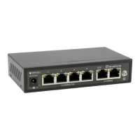
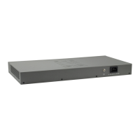
FEP-0631
User manua/QIGl
Installation
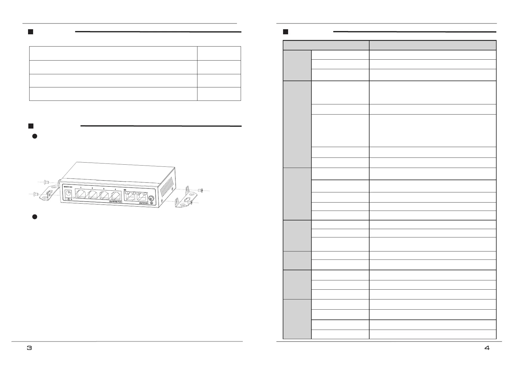
Installation on the wall
1) Use the screws to fix the hanger, follow the figure below;
2) Drill holes on a strong position of wall and then drive the rubber plug into the hole;
3) Drive these screws into the holes.
Self-consumption<5W, PoE output Max.60W
1~4 ports: 10/100Base-TX 30W PoE
RJ45(IEEE802.3af/at PSE)
5~6 ports: 10/100Base-TX RJ45
If detect PD device frozen, restart the device
Extend: 1~4 ports Max. 250m transmission, 1~4 ports are
isolated, only can communicate with the uplink ports; restrain
the network storm; close flow control.
Default: common switch.
VLAN: 1~4 ports are isolated, only can communicate with the
uplink ports; restrain the network storm; close flow control.
Support IEEE 802.3af/at, end-span, single port≦30W
Use cat5e/6, 100m max.(Extend mode max.250m)
IEEE802.3, IEEE802.3u, IEEE802.3z
On RJ45 yellow and green LEDs indicate Link/Act
On RJ45 green LEDs indicate Link/Act,
yellow LEDs indicate PoE
6KV, standard: IEC61000-4-5
6KV: contact / 8KV: air, standard: IEC61000-4-2
Specification
Installation step
Please follow the following steps( take video monitoring for example);
1) Please turn off the signal source and the device's power, installation with power on may damage the device;
2) Use 4 pcs network cables to connect 4 pcs IP cameras with the product's 1~4 RJ45 ports;
3) Use 1 network cable to connect port 5 with NVR, another network cable to connect port 6 with other switch;
4) Connect switch with power adapter;
5) Check if the installation is correct and device is good, make sure all the connection is reliable and power up the system;
6) Make sure every network device power supply works normally.