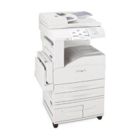
Parts catalog 7-37
7500-XXX
Assembly 17: Covers and operator panel
Asm
Index
Part
number
Units/
mach
Units/ kit
or pkg
Description
17—1 40X2200 1 1 Scanner top rear cover
2 40X2201 1 1 Scanner right cover
3 40X2736 1 1 Operator panel assembly (universal)
Note: This operator panel can be used on any X850 Series product.
Note: This operator panel does not include the model specific bezel.
4 40X2363 1 1 Operator panel controller card assembly
5 40X2364 1 1 Operator panel inverter card assembly
6 40X2362 1 1 Operator panel user touch screen
7 40X2365 1 1 USB connecto2r/housing/cable
8 40X2203 1 1 Operator panel cable assembly
9 40X2399 1 1 USB cable assembly
10 40X2730 1 1 Operator panel bezel (X850e)
10 40X2731 1 1 Operator panel bezel (X852e)
10 40X2732 1 1 Operator panel bezel (X854e)
11 40X2205 1 1 Scanner left cover
12 40X2219 1 1 Scanner interface cable assembly
13 40X2207 1 1 Scanner PS cable assembly
14 40X2206 1 1 Flatbed scanner unit assembly (this comes assembled)
Note: This assembly includes all individual parts on pages 7-38, 7-40, 7-42,
and 7-44.
Warning: In the event of replacement of any one of the following components:
• Operator panel assembly (universal)
• Operator panel controller card assembly
• RIP card assembly
• Interconnect card assembly
Only replace one component at a time. Replace the required component, and perform a POR before replacing a second
component listed above. If this procedure is not followed, the printer will be rendered inoperable. Never replace two or
more of the components listed above without a POR after installing each one, or the printer will be rendered inoperable.
Warning: Never install and remove components listed above as a method of troubleshooting components. Once a
component has been installed in a machine, it cannot be used in another machine. It must be returned to the
manufacturer.

 Loading...


