4-130 Service Manual
7510
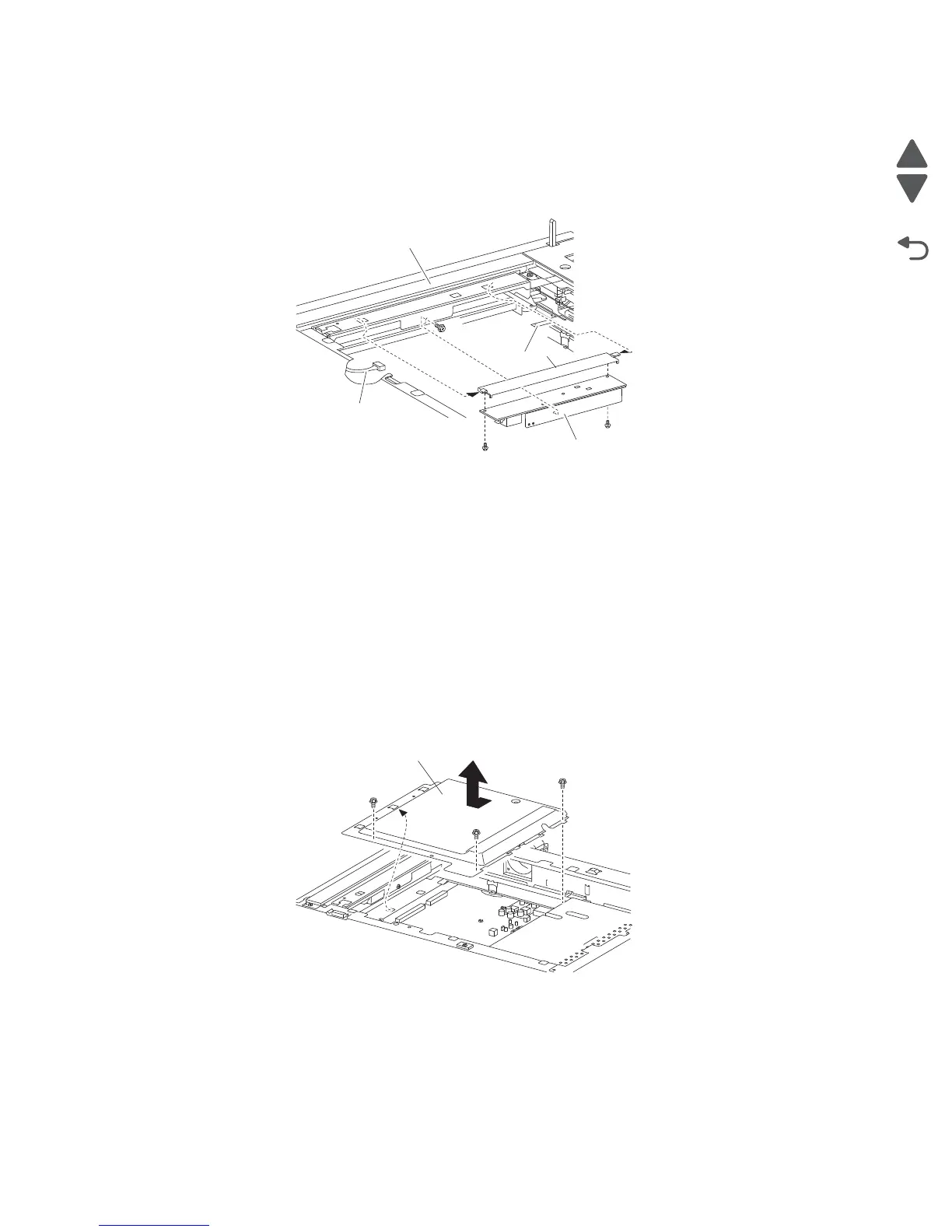
8. Remove the insulator bracket (E).
Note: Before reinstalling the exposure lamp PS card assembly (A), ensure that all connections are properly
connected.
Note: Ensure that all harnesses and cables move freely without binding.
Note: Ensure that the exposure lamp PS card assembly is securely mounted to the scanner carriage (B).
Scanner controller card assembly removal
1. Remove the scanner top rear cover. See “Scanner top rear cover removal” on page 4-125.
2. Remove the large platen glass. See “Large platen glass removal” on page 4-124.
3. Gently move the scanner carriage assembly completely to the left to provide access to the screws.
4. Remove the three screws securing the cover (A) to the scanner unit assembly.
5. Move the cover (A) forward then upward in the direction of the arrow.
6. Remove the cover (A).
7. Remove the four card mounting screws (B) securing the scanner controller card assembly (C) from the rear
of the scanner unit assembly.
8. Remove the screw from the rear securing the scanner controller card assembly (C) to the assembly.
9. Disconnect the four connections from the scanner controller card assembly (C).
10. Remove the seven screws securing the scanner controller card assembly (C) to the scanner unit assembly.
11. Remove the scanner controller card assembly (C).
 Loading...