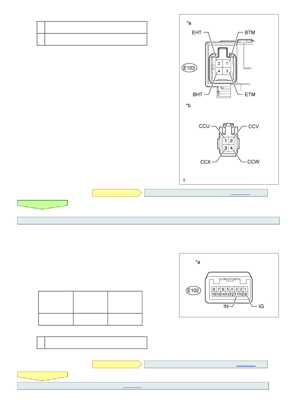
Text in Illustration
*a
Component without harness connected
(Spiral Cable)
*b
Front view of harness connector
(to Heated Steering Wheel Controller)
NG REPLACE SPIRAL CABLE SUB-ASSEMBLY ( Click here)
OK
6.CHECK COMBINATION SWITCH ASSEMBLY
a. Disconnect the combination switch connector.
b. Measure the voltage according to the value(s) in the table below.
HINT:
As the circuit has a diode, perform the measurement in diode test mode and
make sure that the polarity is correct.
Standard Voltage:
Tester Connection
Positive (+) tester
probe - Negative (-
) tester probe
Switch Condition
Specified
Condition
E102-9 (IG) -
E102-11 (IN)
Combination
switch is pushed
Below 1.25 V
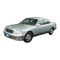
Text in Illustration
*a
Component without harness connected
(to Combination switch)
NG REPLACE COMBINATION SWITCH ASSEMBLY (Click here)
OK
REPLACE HEATED STEERING WHEEL CONTROLLER (Click here)