Installation
GA09420_002_C0 – (2016-10) –
Leybold
23
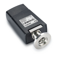
Lock the Profibus (and sensor) cable connector.
The transmitter can now be operated via Profibus interface (→ 32).
3.2.3 Using the Optional Power Supply (With RS232C Line)
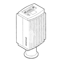
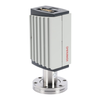
The optional 24 V power supply (→ 43) allows RS232C operation of the ITR 90
transmitter with any suitable instrument or control device.
The instrument or control device needs to be equipped with a software that sup-
ports the RS232C protocol of the transmitter (→ 29).
Technical data
Mains connection
Mains voltage 90 … 250 VAC 50 … 60 Hz
Mains cable 1.8 meter (Schuko DIN and U.S. con-
nectors)
Output (operating voltage of transmitter)
Voltage 21 … 27 VDC, set to 24 VDC
Current Max. 1.5 A
Transmitter connection
Connector D-Sub, 15-pin, female
24 VDC cable 5 m, black
Connection of the instrument or control
device
RS232C connection D-Sub, 9-pin, female
Cable 5 m, black, 3 conductors, shielded
Wiring diagram
N
PE
DC
AC
GND
+24 V
PE
ITR 90
D-Sub,
15 pins
RS232C
D-Sub, 9 pins
Mains
90 ... 250 VAC
50 ... 60 Hz
 Loading...