GA 05.218/3.02 - 11/97
Connection
17
Key to Fig. 14
1 Relay
2 Jumper
3 Connection plug for the RS 232 interface
4 Fuses
F7 Fuse for 15 V at Pin 20 of the
terminal strip REMOTE
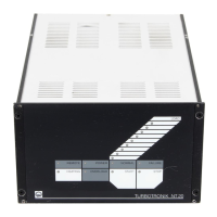
Fig. 14 Position of the jumper for the relay failure;
top view into the TURBOTRONIK
Terminals No.
Terminals No.
Terminals No.
active = 13 V ... 33 V
inactive = 0 V ... 7 V
active = 0 V ... 7 V
inactive = 13 V ... 33 V
active = 13 V ... 33 V
inactive = 0 V ... 7 V
Active control with a voltage signal;
LEYBOTRONIK I compatible
Via continuous contact, remote control
via key; passive control with contacts
Via continuous contact, ON/OFF
switch; passive control with contacts
Fig. 13 Connection of the remote control
 Loading...