GA 05.218/3.02 - 11/97
2.4
NT 340 M & NT 340 MA with-
out temperature control:
Connecting the Cooling, Ven-
ting Device and the Flange
Heater
Cooling
The mains power supply to the socket (3/10) is switched
on as soon as the TURBOVAC acceleration sequence
begins; max. load 100 VA. The relevant fuse (3/12) is
below the socket.
The power supply to the socket is switched off once the
TURBOVAC has come to a standstill and when the
power switch is turned off.
A magnetic valve for the water cooling or a fan can be
connected to the socket (3/10).
Venting
The mains power supply to the socket (3/13) is switched
on without any delay when START is activated. The
power is turned off when STOP or FAILURE are activa-
ted; max. load 20 VA. The relevant fuse (3/12) is below
the socket.
Caution
Any interruption in power, no matter how
short, will cause the pump to be vented.
Power Failure Airing Valve
If the TURBOVAC is operated without purge gas a power
failure airing valve can be connected to socket (3/13)
VALVE.
Purge Gas- and Venting Valve
When operating the TURBOVAC with purge gas it must
be vented via the purge gas and venting valve.
Delayed Venting Device and Venting Valve
When shutting down or in case of a power failure the
connection of the delayed venting device allows for set-
ting the start and duration of the venting sequence in
order to protect a system or a process-procedure.
The presetting time can vary between 3 to 15 minutes.
A short power failure does not entail an unwanted ven-
ting.
Connect the delayed venting device to (3/13).
Connection
8
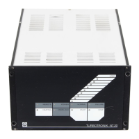
Key to Fig. 3
1 Power switch
2 Relay contact for forevacuum pump
ON/OFF
3 Connection for supply of the
TURBOVAC
4 LED red, magnetic bearing active
5 Connection for the magnetic bearing
of the TURBOVAC
6 Connection socket for RS 232 inter-
face
7 Connection terminal strip
8 Potentiometer for setting
the delay time
9 Parameter selection for RS 232
interface
10 Connection for fan or solenoid valve
for water cooling
11 Connection for heating
12 Fuses
13 Connection for venting valve
14 Connection for power linecord
15 Plug for selecting the mains
voltages with integrated fuse
Fig. 3 TURBOTRONIK NT 340 M & MA, rear panel
 Loading...