EasyManua.ls Logo

LFE 2000 Series - Page 48

LFE 2000 Series
155 pages
Print Icon
To Next Page IconTo Next Page
To Previous Page IconTo Previous Page
Loading...
958-l
I REV il
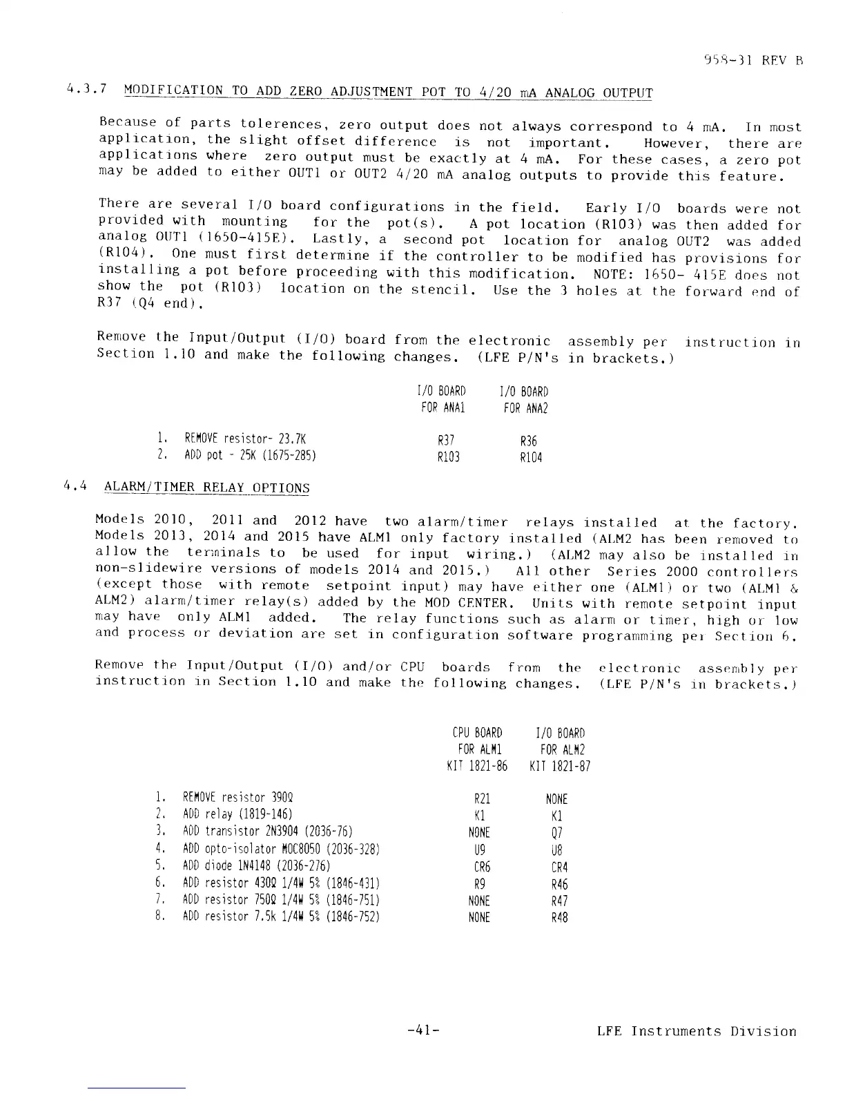
4.3
.7
MODIFICATION
TO
ADD
ZERO
ADJUSTMENT
PoT
TO
41 20
nA ANALOG
Because
of
parts
tolerences,
zero
output
does
not
always correspond
to
4
mA.
In most
applicatron,
the sllght
offset
di.fference
is
not
lmportant. However,
there are
applicatjons
where
zero
output
must
be
exactly
at
4 mA. For these
cases,
a
zero
pot
rnay
be
added
to either
OUTI
or oUT2
4120
mA
analog
out.puts
to
provide
thrs
feature.
There
are
several
I/o
board
confrguratrons
in the
field.
Earrv
rlo
boards
\rere
not
provided
with
mounting
for
the
pot(s).
A
pot
location
(R103)
was
then
added for
analog
OtlTl
(1650-415E).
Lastly,
a
second
pot
location
for
analog
0UT2
was added
(R104).
One
must
firsL
determi-ne
if
the controller
to be
modified
has
provisrons
for
r-nstalling
a
pot
before proceedrng
with
this
modificatlon.
NOTE:
1650-
415E
does not
show
the
pot
(R103)
location
on
the stencil.
Use
the 3 holes
at the
forwarcl end
of
R37
(Q4
end).
Renrove
the
Input/Output
(rlo)
board
from
the
electronic
assembly
per
instructlon
rn
Sectlon
1.10
and
make
the
following
changes.
(LFE
p/N's
in brackets.
)
OUTPUT
1,
Rtl'10V[
resistor-
23,7K
2.
ADD
pot
-
251(
(1675-285)
I/O
EOARD
I/O
BOARD
TOR
A|'lA1
FOR
ANA2
R37
R36
R103
R104
4.4
ALARM/rrMER
RELAY
_qruqry!
Models
2010,
201
I
and
2012
have
two
alarm/timer
relays
installed
ar
the factory.
Models
2013,
2014
and
2015
have
ALMI
only
factory
instalied
(ALM2
has
been
renioved t9
allow
the t_ennlnals
to
be used
for
input
wlring.)
(ALM2
may
also
be
tnstalled
rrr
non-slldewire
verslons
of
models
2014
and
2015.
)
A1l other
Series
2000
controllers
(except
those
wjth
remote
setpoint
input)
may
have either
one
(ALMl)
or two
(Ai,Ml
&
ALM2)
alarrn/t1mer
relay(s)
added
by the
MOD
CENTER.
Units
with
remote
setpolnt
input
nray
have
only
ALMI
added.
The relay
functions
such as
alarrn
or timer,
hrgh r,rr low
and
process
or devlation
are set-
in
conflguration
software
programming
per
Sect'ion 6.
Remove
the
Input/Output
(I/O)
and/or
CpU
boards from
the
lnstructron
i-n sectlclrr
l.l0
and
make the
f ollowlng
changes.
electronic
assenrbl
y per
(
t,FE
P/N's in
bracket s
.
)
IPU BOARD
1/O BOARI)
FOR ALI'II
FOR
ALI'12
Krr
1821-86 Kir
1821-87
i, Riltl0V[
resistor
390Q
2, ADD
relay
(1819-146)
3,
ADD
transistor
2N3904
(2036-i6)
4,
ADD opto-isolator
I'10C8050
(2036-32S)
5,
ADD
diode 1|'l4148
(2036-2i
6)
6,
ADD resistor
4304
1/4il
5?
(1846-431)
7 ,
ADD resistor
7500 1/4ll
5?
(1846-i5i)
B,
ADD resistor
7,5k
1/41{
5Z
(1846-752)
R21
|(1
NO|.lI
U9
cR6
R9
|lONI
NOt'lT
N0iiI
K1
Q7
UB
CR4
R46
R47
R4B
-41-
LFE
Instruments
Division