- 21 -
LGE Internal Use OnlyCopyright © LG Electronics. Inc. All rights reserved.
Only for training and service purposes
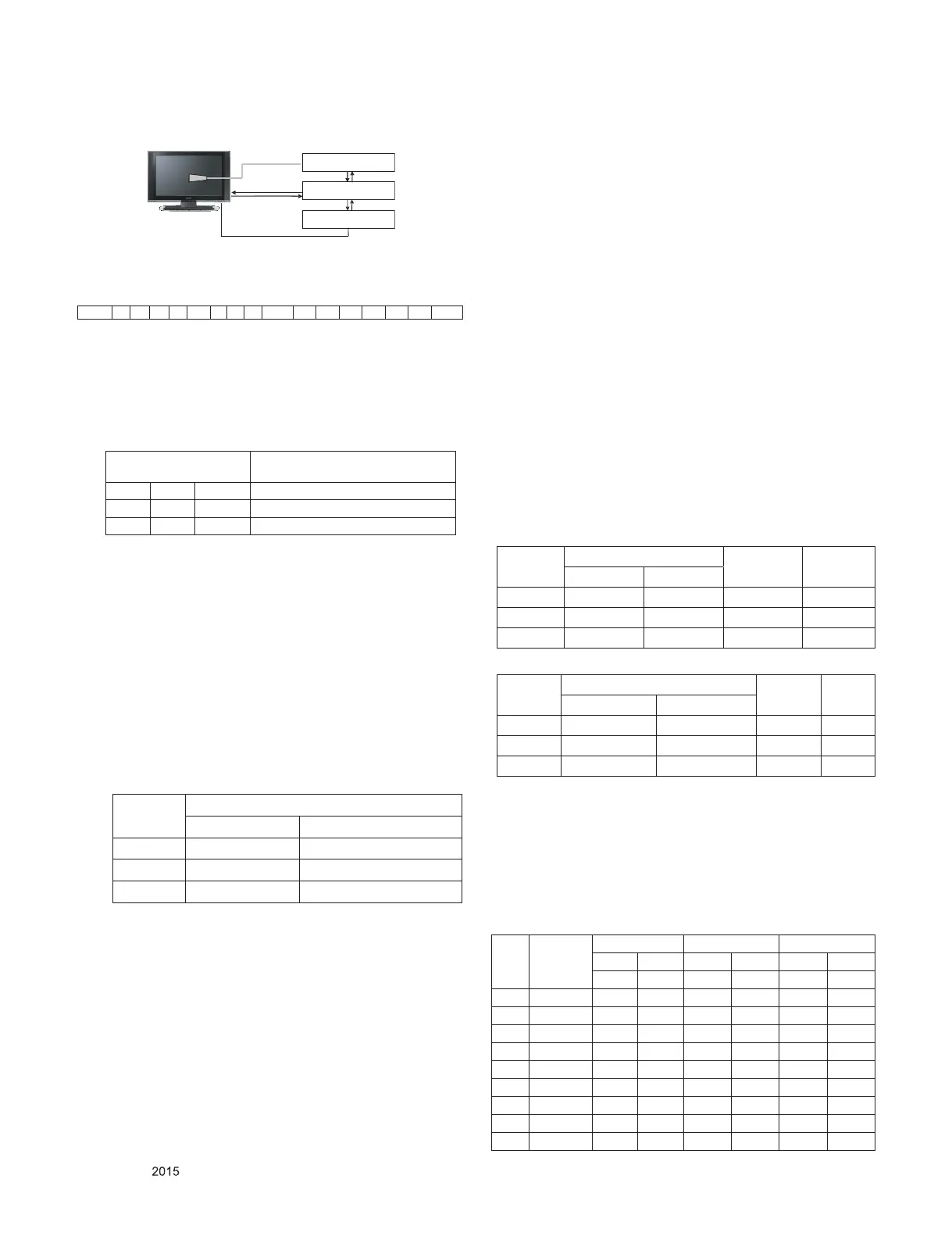
4.2.3. Equipment connection MAP
4.2.4. Adj. Command (Protocol)
<Command Format>
- LEN: Number of Data Byte to be sent
- CMD: Command
- VAL: FOS Data value
- CS: Checksum of sent data
- A: Acknowledge
Ex) ) [Send: va 00 00\r\n]
▪ RS-232C Command used during auto-adjustment.
4.2.5. Adj. method
(1) Auto adj. method
1) Set TV in POWER-ONLY mode using POWER ONLY
key
2) Zero calibrate probe then place it on the center of the
Display
3) Connect Cable (RS-232C to USB)
4) Select Model in “V-com adj. Program” and begin “V-com
adj.”
5) When V-com adj. is complete (OK)
6) Remove probe and RS-232C to USB cable to complete
adj.
▪ V-com Adj. must begin as start command “va 00 00” , and
finish as end command “wb 00 ff”
▪ V-com adjust data(65" inch)
(2) Manual adjustment. method
1) Set TV in Adj. mode using POWER ON.
2) Zero Calibrate the probe of Color Analyzer, then place it
on the center of LCD module within 10 cm of the surface.
3) Press ADJ key → EZ adjust using adj. R/C → 7. White-
Balance then press the cursor to the right(key ►).
(When right key(►) is pressed 216 Gray internal pattern
will be displayed)
4) One of R Gain / G Gain / B Gain should be fixed at 192,
and the rest will be lowered to meet the desired value.
5) Adjustment is performed in COOL, MEDIUM, WARM 3
modes of color temperature.
** G-fix adjustment
Adjust modes (Cool), Fix the G gain to 172 (default data)
and change the others (G/B Gain).
Adjust two modes(Medium / Warm), Fix the one of R/G/B
gain to 192 (default data) and decrease the others.
If internal pattern is not available, use RF input. In EZ Adj.
menu 7.White Balance, you can select one of 2 Test-
pattern: ON, OFF. Default is inner(ON). By selecting OFF,
you can adjust using RF signal in 216 Gray pattern.
▪ Adjustment condition and cautionary items
1) Lighting condition in surrounding area
Surrounding lighting should be lower 10 lux. Try to
isolate adj. area into dark surrounding.
2) Probe location
: Color Analyzer(CA-210) probe should be within 10 cm
and perpendicular of the module surface (80° ~ 100°)
3) Aging time
- After Aging Start, Keep the Power ON status during 5
Minutes.
- In case of LCD, Back-light on should be checked using
no signal or Full-white pattern.
4.2.6. Reference (White balance adjusmtment
coordinate and color temperature)
▪ Luminance : 206 Gray
▪ Standard color coordinate and temperature using CS-1000
(over 26 inch)
▪
Standard color coordinate and temperature using CA-210(CH 14)
4.2.7. EDGE & IOL LED White balance table
▪ Edge & ALEF LED module change color coordinate because
of aging time.
▪ Apply under the color coordinate table, for compensated
aging time.
▪ (Normal line) Edge & ALEF LED White balance table
- gumi(Mar.~Dec.) & Global
Model : (normal line)LGD, CMI
Color Analyzer
Computer
Pattern Generator
RS-232C
RS-232C
RS-232C
Probe
Signal Source
* If TV internal pattern is used, not needed
START 6E A 50 A LEN A 03 A CMD A 00 A VAL A CS STOP
RS-232C COMMAND
[CMD ID DATA]
Explanation
va 00 00 V-com pattern
vb 00 00~ FE V-com adj.(internal Flicker pattern)
wb 00 FF V-com adj. completed
V-com Data
hex dec
Max AB 171
Default 8D 141
Min 6F 111
Mode
Coordinate
Temp ∆uv
x y
Cool 0.271 0.270 13000 K 0.0000
Medium 0.286 0.289 9300 K 0.0000
Warm 0.313 0.329 6500 K 0.0000
Mode
Coordinate
Temp ∆uv
x y
Cool 0.271 ± 0.002 0.270 ± 0.002 13000 K 0.0000
Medium 0.286 ± 0.003 0.289 ± 0.003 9300 K 0.0000
Warm 0.313 ± 0.002 0.329 ± 0.002 6500 K 0.0000
web
OS
2.0
Aging
time
(Min)
Cool Medium Warm
x y x y x y
271 270 286 289 313 329
1 0-2 282 289 297 308 324 348
2 3-5 281 287 296 306 323 346
3 6-9 279 284 294 303 321 343
4 10-19 277 280 292 299 319 339
5 20-35 275 277 290 296 317 336
6 36-49 274 274 289 293 316 333
7 50-79 273 272 288 291 315 331
8 80-119 272 271 287 290 314 330
9 Over 120 271 270 286 289 313 329
 Loading...