126 | LOW STATIC
MULTI V Ducted Indoor Unit Engineering Manual
Due to our policy of continuous product innovation, some specications may change without notication.
© LG Electronics U.S.A., Inc., Englewood Cliffs, NJ. All rights reserved. “LG” is a registered trademark of LG Corp.
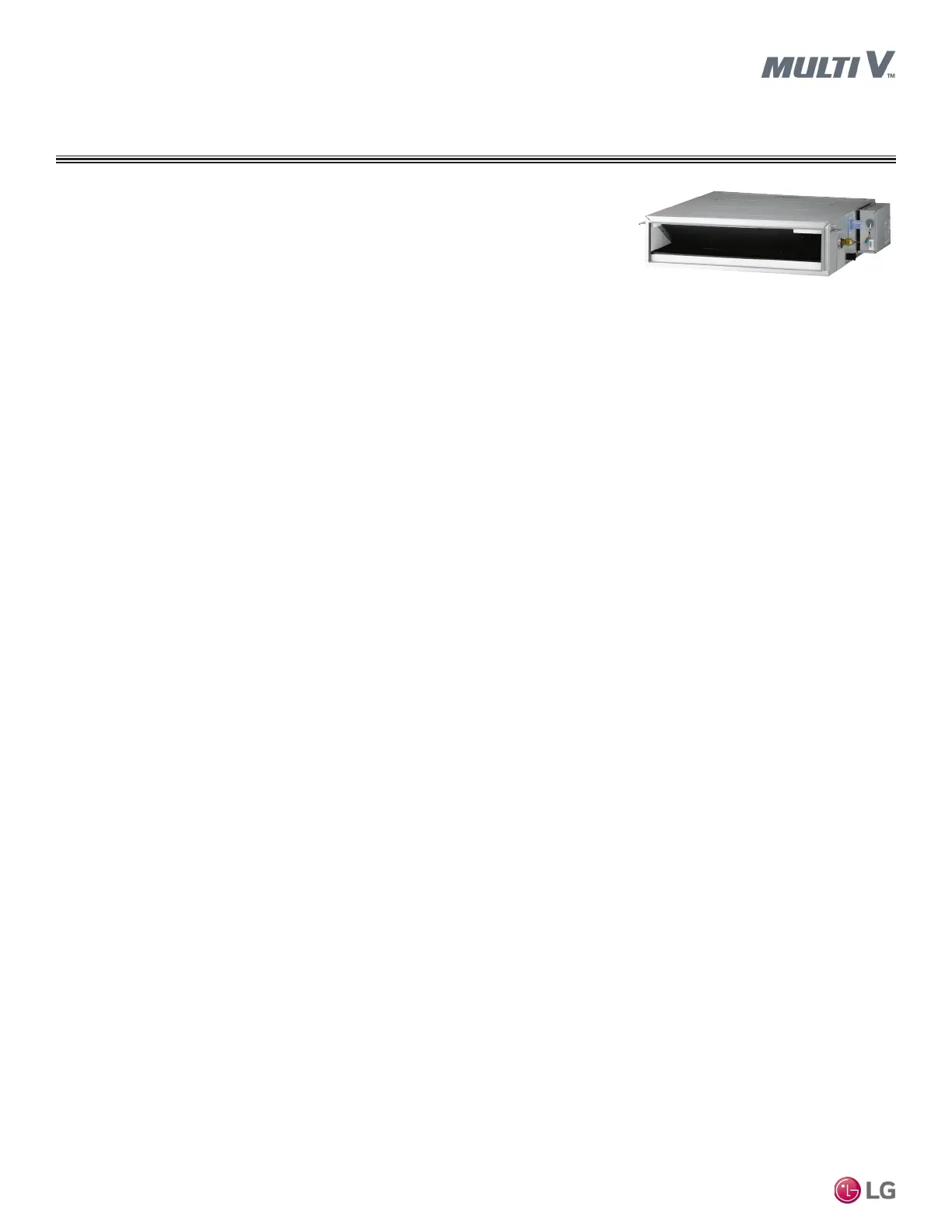
DUCTED LOW STATIC
Mechanical Specications
Casing
The case is a low profile design with a maximum height of eight
inches designed to mount concealed above the finished ceiling. Fan
supply air is front horizontal with a rear horizontal field convertible
to a bottom return. The unit is manufactured with coated metal. Cold
surfaces are covered with a polystyrene insulating material. The
case is provided with hanger brackets designed to support the unit
weight on four corners. Hanger brackets have pre-punched holes
designed to accept field supplied all-thread rod hangers.
Fan Assembly and Control
The unit has Sirocco fans made of high strength ABS HT-700
polymeric resin. Fans are directly driven and mounted on a common
shaft. The fan motor is a Brushless Digitally-Controlled (BLDC)
design with permanently lubricated and sealed ball bearings. The fan
motor includes thermal, overcurrent and low RPM protection. The
fan/motor assembly is mounted on vibration attenuating rubber grom-
mets. The fan impeller is statically and dynamically balanced. The fan
speed is controlled using a microprocessor based direct digital con-
trol algorithm that provides a high fan speed in cooling thermal ON
and low fan speed in cooling thermal OFF, high fan speed in heating
thermal ON and fan off in heating thermal OFF. The fan speeds can
be eld adjusted between low, medium, and high speeds and DIP
switch settings will allow the fan to run constantly during defrost or
oil return modes. Each setting can be eld adjusted from the factory
setting (RPM / ESP) to compensate for resistance to airow caused
by eld connected ductwork or other airow restricting devices.
Air Filter
Return air is filtered with a removable, washable filter with anti-fun-
gal treatment.
Microprocessor Controls
The unit is provided with an integrated microprocessor-based con-
troller. The controller is capable of performing functions necessary
to operate the system without the use of a wall-mounted controller.
A temperature thermistor is factory-mounted in the return air stream.
All unit operation parameters, excluding the unit operating schedule,
are stored in non-volatile memory resident on the unit microproces-
sor. Operating schedules are stored in select models of the optional,
wall-mounted, local, or central controller. The field-supplied commu-
nication cable between the indoor unit(s) and outdoor unit is to be
a minimum of 18 AWG, 2 conductor, stranded and shielded cable
(RS-485), terminated via screw terminals on the control boards.
The microprocessor control provides the following functions: auto
addressing, self-diagnostics, auto restart following power restoration,
test run, and will operate the indoor unit using one of five operating
modes:
1. Auto Changeover (Heat Recovery only)
2. Heating
3. Cooling
4. Dry
5. Fan Only
For Heat Recovery systems the Auto Changeover setting automati-
cally switches control of the indoor unit between cooling and heating
modes based on space temperature conditions.
For Heat Pump systems, heated or cooled air delivery is dependent
upon outdoor unit operating mode.
In Heating mode, the mi-
croprocessor control will
activate the indoor unit
when indoor room tem-
perature falls below set-
point temperature and
signals the outdoor unit to begin heating cycle. The indoor unit fan
operation is delayed until coil pipe temperature reaches 76ºF. Signif-
icant airflow is generated when pipe temperature reaches 80°F. In
lieu of factory return air thermistor, screw terminals on the micropro-
cessor circuit board accommodate various models of wall-mounted
local controllers and/or a wall-mounted remote temperature sensor.
The unit microprocessor is capable of accepting space temperature
readings concurrently or individually from either:
1. Wall-mounted wired controller(s)
2. Factory mounted return air thermistor or the optional wall-
mounted wired remote temperature sensor.
A single indoor unit has the capability of being controlled by up to
two local wired controllers. The microprocessor controls space tem-
perature using the value provided by the temperature sensor sensing
a space temperature that is farthest away from the temperature
set-point. The microprocessor control provides a cooling or heating
mode test cycle that operates the unit for 18 minutes without regard
to the space temperature. If the system is provided with an optional
wall-mounted or central controller, displayed diagnostic codes are
specific, alpha numeric, and provide the service technician with a
reason for the code displayed.
Condensate Lift/Pump
The indoor unit is provided with a factory installed and wired
condensate lift/pump capable of providing a minimum 27.5 inch lift
from the bottom exterior surface of the unit casing. The lift pump
comes with a safety switch that will shut off indoor unit if condensate
rises too high in the drain pan.
Condensate Drain Pan
The condensate drain pan is constructed of high impact polystyrene
resin (HIPS).
Coil
The indoor unit coil is constructed with grooved design copper tubes
with slit coil fins, two (2) to three (3) rows, eighteen (18) to
twenty-one (21) fins per inch.
Controls Features
• Auto changeover
(Heat Recovery only)
• Auto operation
• Auto restart
• External on / off control
• Dual thermistor control
• Dual set-point control*
• Filter life display*
• Multiple auxiliary heater
applications*
• Group control
• Wi-Fi compatible
• Auto fan
• Leak detection
• External static pressure control
• Hot start
• Self diagnostics
• Timer (on / off)
• Weekly schedule
• Fan speed control
• Ventilation (outside air)
*To enable Generation 4 features, out-
door unit DIP Switch No. 3 must be set
to ON. Please refer to the Multi V IV,
Multi V Water IV, Multi V S Engineer-
ing Manual for additional information.
 Loading...