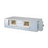
60 Synchro Air Conditioner
Installation
Auto addressing
Auto addressing work should be done for simultaneous operation.
Addressing work assigns address to each Indoor Unit.
When firstly installing product or replacing the Indoor Unit PCB.
3. Auto Addressing Method
Table.a ZONE SW1 Setting
TEST_SW1
LED01T
JIG_SW
1234
ZONE SW1
Main PCB
Main PCB
Fig.a Outdoor PCB diagram
C
B
A
1. JIG_SW Setting
Check the JIG_SW to the right, or not set the JIG_SW to
the right.( A )
2. ZONE SW1 Setting
Set the ZONE SW1 as below Table.a ( B )
❈ S/W1 is not used.
❈ 1 means S/W up.
0 means S/W down.
1. Indoor unit connection numbers separation s/w
Accordingly insert the Number pin numbers as below in
accordance with the indoor unit connection numbers.( A )
(Inserting order is irrespective.)
3. Auto Addressing Method
1) Turn main power on.
2) Press the S/W_ADDRESSING for about
5~7 seconds( C )
3) Turn the Indoor unit on after 1~2minutes after
pressing
the s/w.(If performing the ADDRESSING work at the
PCB, the green LED rapidly flickers.)
2. Operation method of pipe length s/w
Convert the s/w toward "long pipe" direction when
installing more than main pipe of 30m ( B ).
* Work procedure
1) Set JIG_SW and ZONE SW1 correctly.
2) Turn on main power.
3) Press the TEST_SW1 for about 3 seconds within 3minutes After
main power on.( C )
4) After step 3), the LED01T(green LED) rapidly flickers.
When Addressing work is done, green LED is off, else LED stops
flickering and lights continuously.
5) If you fail to perform the Addressing work,
repeat step 2),3).
(Outdoor PCB Board)
Connection
numbers
AUUW4860/AUUW6060
AUUH488B/AUUH7280/AUUH10080
ZONE SW1
Indoor Unit No.
12
34
x0
00
x1
00
x
1
10
2(Duo)
1(Single)
3(Trio)
4(Quartet)
12
3 4
12
3
4
x
1
11
12
3
4

 Loading...