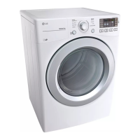
Do you have a question about the LG DLE1501W and is the answer not in the manual?
Ensure grounding wires, screws, straps, clips, nuts, or washers are returned to their original position and properly fastened.
Steps to follow if you smell gas: evacuate, do not use appliances or phones, and call the gas supplier.
Guidelines for handling sensitive electronics to prevent damage from ESD, including using an anti-static wrist strap.
Details on the optional dryer rack accessory and where to find usage instructions.
Instructions for connecting the dryer using a 4-wire receptacle (NEMA type 14-30R).
Instructions for connecting the dryer using a 3-wire receptacle (NEMA type 10-30R).
Procedure for connecting the gas supply pipe to the gas dryer, including connector types and safety checks.
Steps for connecting the cold water inlet hose for steam models, including pressure requirements.
Tests for thermal cut-offs, thermostats, and safety limit components.
Procedures for testing door switches, idler switches, and inlet valves.
Testing procedures for the heater, thermistor, and temperature sensing components.
Diagnostic tests for motor operation and gas valve resistance.
Tests for the igniter component and frame detect sensor functionality.
Schematic illustrating the electrical connections for the electric dryer model.
Schematic illustrating the electrical connections for the gas dryer model.
Explanation of the FlowSense function for detecting duct blockages and alarms.
Procedure for testing the dryer's exhaust system adequacy after installation.
Troubleshooting guide for issues related to the flow sensor indicator light and duct blockages.
Steps to enter and activate the dryer's diagnostic testing mode.
Procedure for testing the 120V AC electrical supply and controller connections.
Procedure for measuring thermistor resistance to diagnose temperature sensing issues.
Testing the motor function by measuring resistance and checking for drum rotation and fan operation.
Procedure for testing the moisture sensor's IMC ratio and display value.
Testing the door switch resistance for proper sensing of door opening and closing.
Testing heater switch resistance to diagnose heating operation issues in electric models.
Testing gas valve voltage and resistance to diagnose heating issues in gas models.
Instructions for adjusting gas valve settings between natural gas and propane.
Procedure for replacing the gas orifice to convert between natural gas and propane.
Steps to remove and disassemble the rear panel of the dryer.
Procedure for removing and disassembling the top plate assembly.
Instructions for removing and disconnecting the main printed circuit board (PCB).
Steps to remove and disassemble the dryer's control panel.
Procedure for removing and disassembling the dryer's top cover.
Instructions for removing the inner top plate and associated components.
Steps to remove and disassemble the dryer's cabinet cover.
Procedure for disassembling the front section of the tub drum assembly.
Instructions for removing the drum assembly, including belt and pulley adjustments.
Steps for replacing the interior drum lamp bulb.
Procedure for changing or installing the dryer's exhaust duct system.
Steps to remove and disassemble the lint filter assembly and electrode sensor.
Instructions for removing and disassembling the blower housing, fan, and motor.
Steps to remove and disassemble the dryer's back cover.
Procedure for removing and disassembling the air duct components.
Instructions for removing and disassembling the dryer drum rollers.
Exploded view of the control panel and related plate components for electric models.
Exploded view of the control panel and related plate components for gas models.
Exploded view of the cabinet and door assembly for electric dryer models.
Exploded view of the cabinet and door assembly for gas dryer models.
Exploded view of the drum and motor assembly for electric dryer models.
Exploded view of the drum and motor assembly for gas dryer models.
| Door hinge | Right |
|---|---|
| Drum volume | 206.7 L |
| Display type | LED |
| Loading type | Front-load |
| Drying system | - |
| Product color | White |
| Reversible doors | Yes |
| Appliance placement | Freestanding |
| Cycle time | - min |
| Noise level | - dB |
| Drum capacity | 10.1 kg |
| Number of drying levels | 5 |
| Number of drying programs | 8 |
| Current | 30 A |
| Heat source | Electric |
| AC input voltage | 240 V |
| Energy consumption | - kWh |
| Package depth | 793.8 mm |
| Package width | 749.3 mm |
| Package height | 1092.2 mm |
| Package weight | 66814 g |
| Depth | 735 mm |
|---|---|
| Width | 685.8 mm |
| Height | 1020.8 mm |
| Weight | 58513 g |
| Depth with door open | 1276.4 mm |