EasyManua.ls Logo

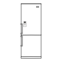
LG GB7143**AV Series User Manual

LG GB7143**AV Series
74 pages
To Next Page IconTo Next Page
Page #1 background imageLoading...
Page #1 background image
CAUTION
BEFORE SERVICING THE UNIT, READ THE "SAFETY
PRECAUTIONS" IN THIS MANUAL.
http://biz.lgservice.com
MODEL :
COLOR :
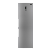
REFRIGERATOR
SERVICE MANUAL
Ref. No.
GB7143**GZ
GB7143**HZ
Ref. No.
GB7143**RZ
GB7138**XZ
Ref. No.
GB7143**RZ
GB7138**XZ
Ref. No.
GB7143**AV
GB7143**BV

Questions and Answers:

LG GB7143**AV Series Specifications

General IconGeneral
Climate ClassSN-T
RefrigerantR600a
Door FinishStainless Steel
Linear CompressorYes
Interior LightingLED
Width91 cm
Depth74 cm

Summary

SAFETY PRECAUTIONS

SERVICING PRECAUTIONS

DISASSEMBLY

COMPRESSOR

1. Inverter Linear Compressor

Checks and methods for testing the inverter linear compressor's functionality.

2) Method to Determine Defect of Inverter Linear Drive

Procedures to determine defects in the inverter linear drive system.

Heavy Repair Method of Refrigerator by Application of Refrigerant

2) Features of R600a Refrigerant

Properties, hazards, and characteristics of R600a refrigerant.

2. Heavy Repair SVC Method

General Service (SVC) method for R600a type refrigerators.

1) Returnof Refrigerator Refrigerant

Procedure for safely discharging and recovering refrigerant from the refrigerator.

2) Returnof Remained Refrigerant

Process for recovering any remaining refrigerant from the system pipes.

6) Refrigerant Charging

Steps for accurately charging the correct amount of refrigerant into the system.

7) Leak Inspection and Cycle Check

Procedures for inspecting for refrigerant leaks and checking the cycle's normal operation.

9) Cautions in Heavy Repair Service

Critical safety precautions and warnings for heavy repair procedures.

CIRCUIT DIAGRAM

TROUBLESHOOTING (Mechanical Part)

2. SERVICE DIAGNOSIS CHART

A chart for diagnosing common complaints and their corresponding remedies.

REFRIGERATING CYCLE

Troubleshooting Chart

A chart detailing causes, states, and remarks for refrigerating cycle problems.

Leakage Detection

Methods and steps for detecting refrigerant leakage in the system.

MICOM FUNCTION & PCB CIRCUIT EXPLANATION

1) FUNCTION

Explanation of the MICOM control functions, display modes, and initial settings.

MICOM Error Code

1. Error Code Summary

A summary table of MICOM error codes and their relation to load control components.

Troubleshooting With Error Display

1. Freezer Sensor Error (FS)

Troubleshooting steps and SVC actions for a Freezer Sensor Error (FS).

2. Fridge Sensor Error (rS)

Troubleshooting steps and SVC actions for a Fridge Sensor Error (rS).

3. RT Sensor Error (rt)

Troubleshooting steps and SVC actions for an RT Sensor Error (rt).

4. Defrost Sensor Error (dS F)

Troubleshooting steps and SVC actions for a Defrost Sensor Error (dS F).

5. Defrost Heater Error (dH F)

Troubleshooting steps and SVC actions for a Defrost Heater Error (dH F).

6. Defrost Sensor Error (dS r)

Troubleshooting steps and SVC actions for a Defrost Sensor Error (dS r).

7. Defrost Heater Error (dH r)

Troubleshooting steps and SVC actions for a Defrost Heater Error (dH r).

8. Freezer Fan Error (FF)

Troubleshooting steps and SVC actions for a Freezer Fan Error (FF).

9. Condenser Fan Error (CF)

Troubleshooting steps and SVC actions for a Condenser Fan Error (CF).

10. Refrigerator Fan Error (rF)

Troubleshooting steps and SVC actions for a Refrigerator Fan Error (rF).

11. Communication Error (Er CO)

Troubleshooting steps and SVC actions for a Communication Error (Er CO).

Troubleshooting Without Error Display

Related product manuals