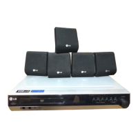
Do you have a question about the LG LH-C6231P and is the answer not in the manual?
Comprehensive guidelines for safe servicing of video products, covering fire, shock, X-radiation, and implosion hazards.
Guidelines for safely transporting and storing the pick-up unit to prevent damage.
Specific precautions and procedures for repairing the pick-up, including handling laser beams and cleaning.
Essential preparations for CD player repairs, focusing on component sensitivity to static electricity.
Important steps and precautions to follow during CD player repair, including grounding and tool usage.
Essential safety measures and general precautions to be followed before and during servicing.
Procedures to prevent damage to ES devices from static electricity during servicing.
Details on power, dimensions, mass, operating conditions, and timer.
Technical specifications for the DVD playback section, including laser and signal system.
Technical specifications for the VCR section, including head system and recording time.
Technical specifications for the tuner section, covering tuning range and intermediate frequency.
Technical specifications for the amplifier section, detailing stereo and surround sound output.
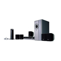
Technical specifications for the satellite and subwoofer speakers, including impedance and power.
Troubleshooting flow chart for audio amplifier issues, guiding through checks and solutions.
Detailed procedures for electrical adjustments, including servo adjustment and PG adjustment.
Troubleshooting steps for the auto-stop function in the VCR system, including waveform checks.
Troubleshooting guide for issues with unstable cassette tape loading in the VCR.
Troubleshooting steps for unstable video playback in the VCR's servo circuit.
Diagnostic steps for when the VCR's drum motor fails to operate.
Troubleshooting guide for issues where the VCR's capstan motor does not run.
Troubleshooting steps for when the VCR's key input buttons are not working.
Troubleshooting steps for no video signal in EE mode, checking various circuit paths.
Troubleshooting steps for missing luminance signal during playback.
Troubleshooting steps for missing color signal during playback.
Troubleshooting steps for no video signal during recording.
Troubleshooting steps for no audio output in EE mode, checking various audio circuits.
Troubleshooting steps for no sound during Hi-Fi playback.
Troubleshooting steps for inability to record Hi-Fi audio signals.
Troubleshooting steps for no picture displayed on the TV screen.
Troubleshooting steps for no sound from the tuner/IF circuit.
Troubleshooting flow chart for DVD electrical issues, starting with power and communication checks.
Details and waveforms for system clock, reset, and flash read/write signals.
Displays RS232 waveforms during the downloading procedure.
Displays flash read/write enable signals during download.
Shows the main clock waveform for MT1379 at 27MHz.
Displays waveforms related to tray open and close operations.
Waveforms illustrating the tray closing sequence.
Waveforms illustrating the tray opening sequence.
Sled control signals displayed when no disc is present.
Lens control signals displayed when no disc is present.
Laser power control signals when no disc is present.
Spindle control waveforms when no disc is present.
Tracking control signals for system checking.
Displays the MT1379 video output waveform for full colorbar (CVBS).
Displays the Y component of the MT1379 video output waveform.
Displays the C component of the MT1379 video output waveform.
Shows waveforms related to the audio output from the DAC.
Details and exploded view for the satellite speaker model LHS-C6230T.
Details and exploded view for the passive subwoofer model LHS-C6230W.
Schematic diagram for the U-COM circuit.
Schematic diagram for the function and power circuits.
Schematic diagram for the main amplifier section.
Printed circuit board layout for the main amp and front sections (solder side).
Printed circuit board layout for the main amp and front sections (component side).
PCB layout for function and power boards (solder side).
PCB layout for function and power boards (component side).
Schematic diagram for the system of the VCR.
Schematic diagram for audio and video circuits in the VCR.
Schematic diagram of the VCR power supply section.
Schematic diagram for the Tuner/IF and ACSS circuits.
Schematic diagram for the Hi-Fi and Tuner sections.
Schematic diagram for the A/V jacks and SCART connection.
Printed circuit board layout for the tuner section.
Printed circuit board layout for the VCR section.
Printed circuit board layout for the VCR section (continued).
Schematic diagram for the MPEG processing unit of the DVD player.
Schematic diagram for the servo control system of the DVD player.
Schematic diagram for the audio processing circuits of the DVD player.
Schematic diagram for the interface connections of the DVD player.
Printed circuit board layout for the DVD player (solder side).
Printed circuit board layout for the DVD player (component side).
Exploded view and parts breakdown for the cabinet and main frame assembly.
Overview of VCR deck mechanism part locations, including top and bottom views.
Step-by-step guide for disassembling the VCR deck mechanism components.
Detailed illustration of VCR deck mechanism parts in the top view.
Detailed illustration of VCR deck mechanism parts in the bottom view.
Procedure for disassembling the drum assembly, including the drum motor.
Procedure for removing the plate top assembly of the VCR deck mechanism.
Procedure for disassembling the CST holder assembly in the VCR deck.
Procedure for removing the opener door of the VCR deck mechanism.
Procedure for disassembling the bracket assembly for the L/D motor.
Procedure for disassembling the gear assembly rack for the F/L mechanism.
Procedure for disassembling the arm assembly for the F/L mechanism.
Procedure for disassembling the lever assembly for the S/W switch.
Procedure for disassembling the arm assembly cleaner.
Procedure for disassembling the F/E head assembly.
Procedure for disassembling the base assembly for the A/C head.
Procedure for disassembling the brake assembly T.
Procedure for disassembling the brake assembly RS.
Procedure for disassembling the arm assembly tension mechanism.
Procedure for disassembling the reel S and reel T components.
Procedure for disassembling the base assembly P4.
Procedure for disassembling the opener lid.
Procedure for disassembling the arm assembly pinch.
Procedure for disassembling the lever T/up and arm T/up.
Procedure for disassembling the belt capstan and motor capstan.
Procedure for disassembling the lever F/R.
Procedure for disassembling the clutch assembly D35.
Procedure for disassembling the brake assembly capstan.
Procedure for disassembling the gear drive and gear cam.
Procedure for disassembling the gear sector.
Procedure for disassembling the plate slider.
Procedure for disassembling the lever tension mechanism.
Procedure for disassembling the lever spring.
Procedure for disassembling gear assemblies P2 and P3.
Procedure for disassembling base assemblies P2 and P3.
Procedure for disassembling the base loading mechanism.
Procedure for disassembling the base tension mechanism.
Procedure for disassembling the arm assembly idler.
Lists necessary tools and fixtures for adjusting the VCR deck mechanism.
Procedure to check and adjust the mechanism's alignment position when a tape is ejected.
Steps to prepare the deck mechanism for adjustment, setting the loading state without a tape.
Procedure for checking tape transport torque in various modes for smooth operation.
Procedure to regulate tape height for proper running along the lower drum guide line.
Procedure to ensure accurate tape passage over audio and control tracks in record/playback modes.
Steps to confirm smooth tape passage between guides and pinch roller.
Procedure for precise azimuth adjustment of the A/C head.
Procedure for X-value adjustment to ensure compatibility with other VCR models.
Adjustments required after replacing the drum assembly and video heads.
Procedure to check tape travel after reassembling the deck assembly.
Checks for audio and RF locking times after playback and mode changes.
Procedure to check for tape curling or jamming during operation.
Initial checks for cleaning and lubrication before starting VCR maintenance.
Details on the precision and compatibility requirements for VCR components.
Guidelines for periodic inspection and maintenance schedules based on usage.
Procedures for cleaning video heads and tape transport systems.
Procedures for applying grease to specified locations in the VCR mechanism.
Troubleshooting steps for auto rewind and F/R mode issues in the deck mechanism.
Troubleshooting steps for AUTO STOP, CUE/REV modes, and pinch roller contact.
Troubleshooting steps for cassette loading and CST IN switch issues.
Troubleshooting steps for tape presence sensing, motor rotation, and pulses.
Troubleshooting for cassette insertion issues, including lever and CST switches.
Troubleshooting for cassette ejection issues, checking motor rotation and door operation.
Troubleshooting for cassette loading, opener lid, and gear assembly issues.
Exploded view of the front loading mechanism section of the VCR.
Exploded view of the first part of the moving mechanism.
Exploded view of the second part of the moving mechanism.
Overview of DVD deck mechanism part locations, including top and bottom views.
Step-by-step guide for disassembling DVD deck mechanism components.
Detailed illustration of DVD deck mechanism parts with tray in top view.
Detailed illustration of DVD deck mechanism parts without tray in top view.
Detailed illustration of DVD deck mechanism parts in bottom view.
Procedure for disassembling the holder clamp assembly.
Procedure for ejecting and removing the tray disc.
Procedure for disassembling the base assembly sled.
Procedure for disassembling the rubber rear component.
Procedure for disassembling the frame assembly up/down.
Procedure for disassembling the belt loading mechanism.
Procedure for disassembling the gear pulley.
Procedure for disassembling the gear loading mechanism.
Procedure for disassembling the guide up/down mechanism.
Procedure for disassembling the PWB assembly loading.
Procedure for disassembling the base main assembly.
Exploded view of the DVD deck mechanism.