52
Single Zone Vertical Air Handling Unit - CV Installation Manual
Due to our policy of continuous product innovation, some specifications may change without notification.
©LG Electronics U.S.A., Inc., Englewood Cliffs, NJ. All rights reserved. “LG” is a registered trademark of LG Corp.
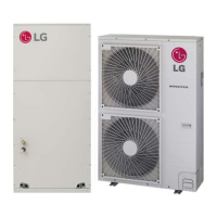
Outdoor Unit Electrical Connections
Connecting Outdoor Unit Wiring
• Verify that main power is completely off and that no power is going through
the Single Zone system before proceeding with these steps. Follow all safe-
ty and warning information outlined at the beginning of this manual. Failure
to do so may cause electric shock, bodily injury and / or death.
• Per code, install a main indoor breaker, and an outdoor service disconnect
that interrupts all power sources simultaneously. There is risk of fire, electric
shock, explosion, physical injury or death.
• Verify that the circuit breaker or some other emergency power cutoff device
is in place before any power wiring is done to the system. Failure to do so
may cause electric shock, bodily injury and / or death.
• Never touch any power lines or live cables before all power is removed
from the system. To do so may cause bodily injury or death.
Air
Conditioner
Main Power Source
Circuit Breaker
Use a circuit breaker
or time delay fuse
Figure 72: Circuit Breaker.
Figure 73: Outdoor Unit Electrical Connections.
1. Remove the front panel and / or control cover from the outdoor unit.
2. Before proceeding, inspect all wiring inside the casing to be sure they
are secure and have not come loose during transportation and installa-
tion of the outdoor unit.
• Loose wires can cause the wiring to burn out quickly.
• Inspect wires for any damage or cracks.
3. Confirm that electrical power supply capacity will be sufficient to run the
unit. See specifications sheets at the beginning of this installation manual
for details on power.
4. Confirm that the right gauge is being used for wiring to proceed.
5. Using a JIS screwdriver, connect all wires as shown at right.
• Each wire must be individually and securely attached to each terminal.
• Secure the cable with the cable tie.
• Pay attention to the location/connection of the green/yellow ground
cable.
• Maintain a minimum of 1/4 inches of wire length from terminal block to
cable bundle.
6. When finished, reattach the control cover and front panel to the outdoor
unit with the screws.
ELECTRICAL SYSTEM INSTALLATION
LVU120HCV, LVU180HCV, LVU240HCV
Cord clamp
Cord clamp
Connecting cable terminal
Connecting cable terminal
LVU300HCV
* Make sure the rubber
bushes are properly
used in knock-out holes
after connecting main
power cable
Power cable terminal
Power cable terminal
 Loading...