29
Installation
Due to our policy of continuous product innovation, some specications may change without notication.
©LG Electronics U.S.A., Inc., Englewood Cliffs, NJ. All rights reserved. “LG” is a registered trademark of LG Corp.
External Connection Diagrams
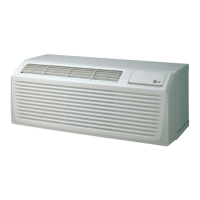
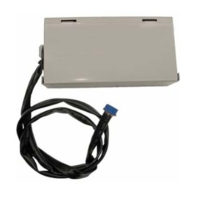
AHU COMMUNICATIONS KIT INSTALLATION
Return Air Temperature Control
Multi V and EEV Kit and DDC (Contact Signal)
L N
Refrigerant Piping (Field Supply)
Wire & Thermistor (LG Supply)
AI/DI/DO Signal (Field Supply)
DX
Coil
Pipe out (Gas) Thermistor
Pipe in (Liquid) Thermistor
Fan control
Return (Room) Thermistor
EEV Kit
Kit
CH 2 A+
CH 2 B-
4(B)
3(A)
Digital
output
On/Off, Defrost, Alarm
GND
12V
SIG
RI1
G
RI3
G
RI4
G
On/Off, Cool/Heat,
Target temp
EEV
Power Supply
N(L2)
L(L1 )
N(L2)
L(L1 )
4(B)
3(A)
IDU A
IDU B
R S T N
Power Supply
1
Fuse
IN T A
IN T B
ACP : CH 1 ~ CH 4
AC SM ART : CH 2
Central Controller
RST N
Wire (Field Supply)
CN_REM O
CN_REM O
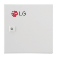
Remote
Controller
Adapter
L
N
Liquid pipe
Gas pipe
MULTI V
Outdoor unit
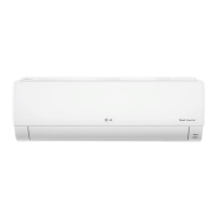
Indoor unit
Indoor unit
Comm. module
Universal
Input
Air Handling Unit
(field supply)
Local AHU
Controller
(Field Supplied)
Notes:
1. The type of power supply of outdoor unit can vary depending on the outdoor model.
2. Please make wiring between LG controller and outdoor unit with the same polarity.
3. LG controller can be optionally applied with DDC.
Compatible EEV Kit models are PRLK048A0 / PRLK096A0 / PRLK396A0
PRLK594A0 is not compatible
 Loading...