10. Accessories
21
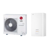
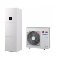
THERMA V Split Type
DHW Tank Integrated Unit
Accessory Part List
10.1.2 Installation Guide
1. ྡ Connect CN_OUT with Outdoor Unit by the cable(provided).
2. ྞ, ྟ Connect RS-485 BUS_A(+) and BUS_(B)(-) with other network products.
(ex. Central Controller, I-Gateway.....)
3. ྠ Select DIP Switch Configuration.
4. Connect CN_PWR with Outdoor PCB Power connector.
5. After Power is ON, check the Communication LEDྙ
• LED2G(Yellow), LED3G(Orange)
– Normal : LED blinks continuously
– Error : Check the DIP Switch setting & wiring connections0
6. ྚ Check RS-485 Communication Status LED:
– Normal : LED blinks when PI485 receives data from central controller.
– Error : Check the wiring connections.
7. Finally if all of the above steps are OK, then tie the cables by tie wraps & clamp
CAUTION
• Install the modbus converter after checking the hole for screw.
10.1.3 DIP Switch Configuration
CAUTION
• Switch No.1 and 2 sould be ON, and all others should be OFF.
• The wrong setting of DIP switches could cause malfunctioning.
Switch setting must be done carefully.
• Push the Reset button after changing the DIP switch.
PP485B00K BRACKET (1EA)
Multi-V
Multi-V
Multi
WIRE ASSY 1(1EA)
SCREW (4EA)
WIRE ASSY 2(1EA) WIRE ASSY 3(1EA)
ON
12345678
Others : Tie Wrap (3 EA) - Cable Tie
Clamp (1 EA)
XYZ[\]^_
vu

 Loading...


