13
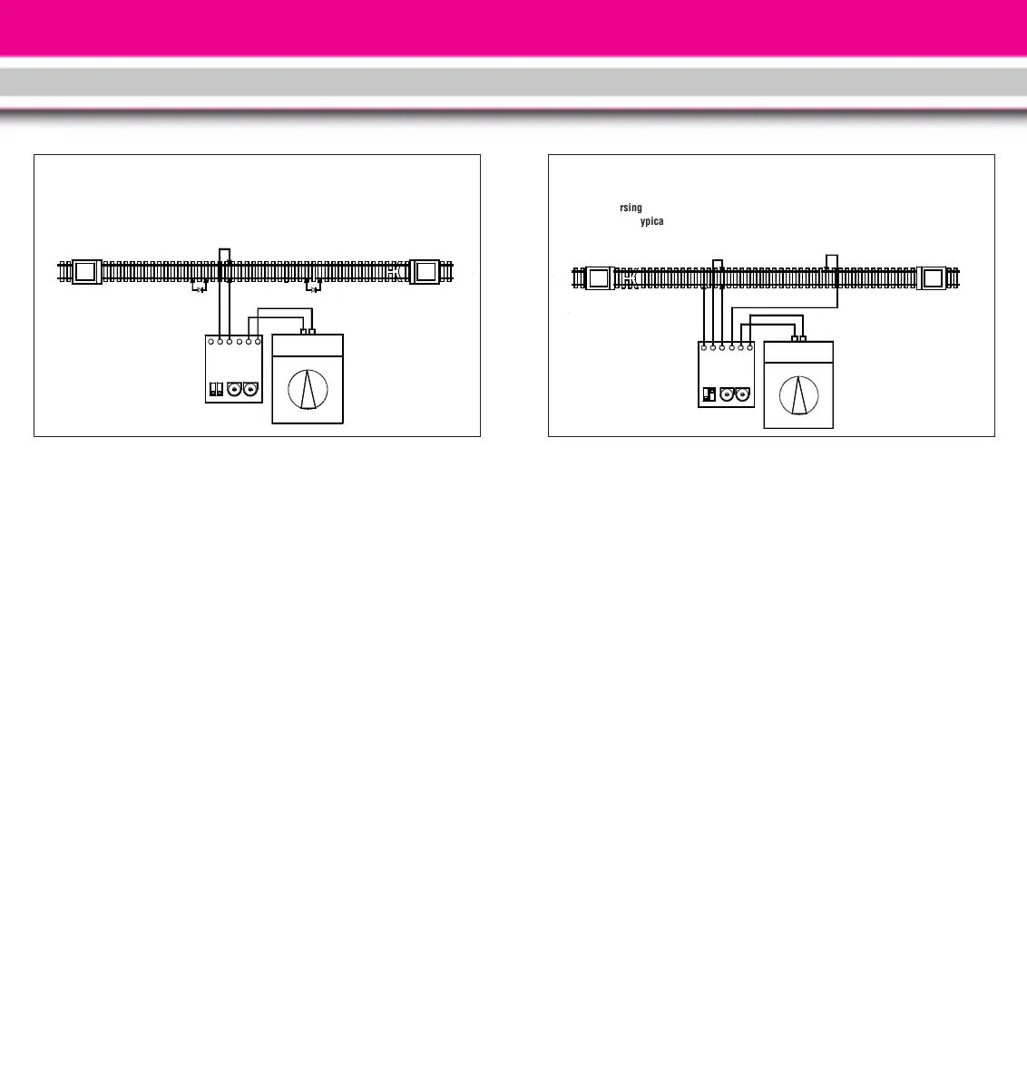
MODE 2 (“WITH PROTOTYPICAL
BRAKING”)
Preparation (Fig. 3)
Hint: To set up this mode, you need
two single-strand wires (for exam-
ple, LGB 50220) to connect the insu-
lated track sections.
1. Loosen the screws on the tracks
and remove the diodes. Install one
of the insulated track sections at
the entrance to each station. The
interrupted rails of the two insulat-
ed track sections must be on
opposite sides of the track. The
track between the stations must
be longer than the train.
2. Connect terminals “sw” (black)
and “ws” (white) on the circuit
board to the insulated track sec-
tions as shown in Fig. 3. Loosen
the screws on the insulated track
sections and trap the wire between
the screw and the rail.
3. Use the blue/red track power cable
to connect the connectors "bl"
(blue) and "rt" (red) of the termi-
nals “A” and “B,” respectively, to
the tracks.
4. Use the blue/red connecting cable
to connect the connectors "bl"
(blue) and "rt" (red) on terminal
“Power” of the circuit board to the
DC output of an LGB throttle or
power pack.
5. Plug the power supply cord into a
house current outlet.
Operation
Place a train on the track between the
stations. Adjust the throttle to a
medium setting. After a short pause,
the train will start and proceed to one
station. When it crosses the insulat-
ed track section, it will slow to a stop.
After the pre-set wait time has
elapsed, it will slowly accelerate in
the opposite direction and proceed to
the other station. The train will shut-
tle between the stations until the
power is switched off.
12
MODE 1 (“BASIC”)
Preparation (Fig. 2)
1. Install one of the insulated track
sections at the entrance to each
station.
2. Use the blue/red track power cable
to connect the connectors marked
“bl” (blue) and “rt” (red) on termi-
nal “A” of the circuit board to the
tracks (Fig. 2).
3. Use the blue/red connecting cable
to connect the connectors "bl"
(blue) and "rt" (red) on terminal
“Power” of the circuit board to the
DC output of an LGB throttle or
power pack.
4. Plug the power supply cord into a
house current outlet.
Operation
Place a train on the track between the
stations. Adjust the throttle to a
medium setting. After a short pause,
the train will start and proceed to one
station. At the station, it will pass
over one of the insulated track sec-
tions and stop. After the pre-set wait-
ing time, it will slowly accelerate in
the opposite direction and proceed to
the other station. The train will shut-
tle between the stations until the
power is switched off.
 Loading...