7
➜
Connecting track contacts:
To connect 17100 EPL Track Contacts to the 55063 MTS Braking Module,
connect the center terminal of the 17100 (marked with a dot) to the terminal
“M” on the 55063. Connect the terminal of the 17100 marked with a triangle
(arrow) facing toward the tracks to one of the terminals “1,” “2” or “S” of
the 55063, as shown in the wiring diagram. Do not use the terminal of the
17100 marked with a triangle (arrow) facing in the direction of the wires.
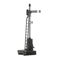
Connecting EPL Supplementary Switches (signals)
For configurations with signal control, the EPL Supplementary Switch on
the signal drive is connected as follows: open contact when signal shows
“Go/Green”; closed contact when signal shows “Stop/Red.”
When operating a stop or slow block with the Multi-Train System, you need
a 55090 MTS Power Extender with updated software for operation with the
MTS Braking Module. If your 55090 MTS Power Extender is not equipped
at the factory with this software, you can have the software updated free
of charge by using the coupon included with these instructions. You also
will receive new instructions for the 55090 MTS Power Extender which
describe the new functions.
Raccordement des contacts de voie:
Pour raccorder les contacts de voie EPL 17100 au module de freinage SMT 55063,
connecter la borne centrale du 17100 (identifiée par un point) à la borne « M »
du 55063. Connecter la borne du 17100 identifiée par un triangle (flèche) faisant face
à la voie à l’une des bornes « 1 », « 2 » ou « S » du 55063, comme il est indiqué
sur le schéma de câblage. Ne pas utiliser la borne du 17100 identifiée par un triangle
(flèche) pointant dans la direction des fils.
Raccordement des interrupteurs supplémentaires EPL (signaux)
Pour les configurations avec commande par signal, l’interrupteur supplémentaire EPL
du dispositif de commande du signal est raccordé comme suit: contact ouvert lorsque
le signal indique « Poursuivre/Vert »; fermé lorsqu’il indique « Arrêter/Rouge ».
En ce qui concerne les positions d’arrêt et les sections de voie avec passage à vitesse
réduite lorsqu’on utilise le système multitrain, il est nécessaire d’utiliser un module
d’augmentation de puissance SMT 55090 avec logiciel dernière version avec le module
de freinage SMT. Si votre module d’augmentation de puissance SMT 55090 n’est pas
d’origine à la dernière version du logiciel, vous pouvez mettre à jour le logiciel gratuitement
en utilisant le coupon joint à cette fiche d’instructions. Vous recevrez également les
nouvelles instructions qui décrivent les nouvelles fonctions du module d’augmentation
de puissance SMT 55090.
© DiskArt™ 1988
 Loading...