EasyManua.ls Logo

Liberty Safe Safe Power Outlet Kit User Manual

Liberty Safe Safe Power Outlet Kit
9 pages
To Next Page IconTo Next Page
Page #1 background imageLoading...
Page #1 background image
INSTALLATION AND OPERATION MANUAL
www.LibertySafe.com (800) 247-5625
©2014 Liberty Safe & Security Products, Inc.
PN 11015-001
Ca t- 5USB 2.0
ANTENNA
Question and Answer IconNeed help?

Do you have a question about the Liberty Safe Safe Power Outlet Kit and is the answer not in the manual?

Liberty Safe Safe Power Outlet Kit Specifications

General IconGeneral
Power Outlets2
USB Ports2
Cord Length6 feet
Voltage120V
Installation TypeInternal
CompatibilityLiberty Safes
Power Outlet TypeStandard electrical outlet
UsageProvides power inside safe for electronics

Summary

POWER OUTLET KIT PARTS

Cover Plate and Screws

Includes components for covering the installed outlet kit.

Hole Saw Centering Guide

Accessory for accurate drilling of the installation hole.

Screw and Spacer Sets

Various screw and spacer combinations for different safe wall thicknesses.

Hub A and Hub B Components

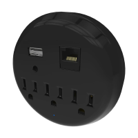
The main power outlet hub and its connected base unit.

Power Cord and Guide Rod

Power cable for the kit and a rod for hole saw guidance.

GETTING STARTED

Tools Required But Not Included

List of necessary tools not provided with the kit for installation.

INSTALLATION GUIDE - INITIAL PREPARATION

Steps 1-5: Hole Preparation and Fabric Marking

Initial steps for safely preparing the safe's interior wall for installation.

INSTALLATION GUIDE - CUTTING AND ASSEMBLY

Steps 6-7: Guide Rod and Hole Saw Usage

Using the guide rod and hole saw for precise cutting through the safe wall.

Steps 8-11: Fabric Cutting and Hole Saw Alignment

Detailed process for cutting interior fabric and aligning the hole saw.

INSTALLATION GUIDE - ASSEMBLY AND MOUNTING

Steps 12-13: Fireboard Removal and Debris Cleanup

Removing fireboard layers and cleaning the installation area.

Steps 14-17: Hub Assembly with Spacers

Assembling the Hub A and Hub B units using screws and correct spacers.

INSTALLATION GUIDE - FINAL INSTALLATION

Steps 18-21: Tightening, Insertion, and Cover Plate

Finalizing the mounting of the outlet kit and securing the cover plate.

Steps 22-23: Final Check and Power Connection

Verifying the installation and connecting the power cord to an outlet.

POWER OUTLET SURGE PROTECTOR

LIMITED LIFETIME MANUFACTURER'S WARRANTY

USB CONNECTION SPECIFICATIONS

USB SUPPORTED DEVICES AND USAGE