7
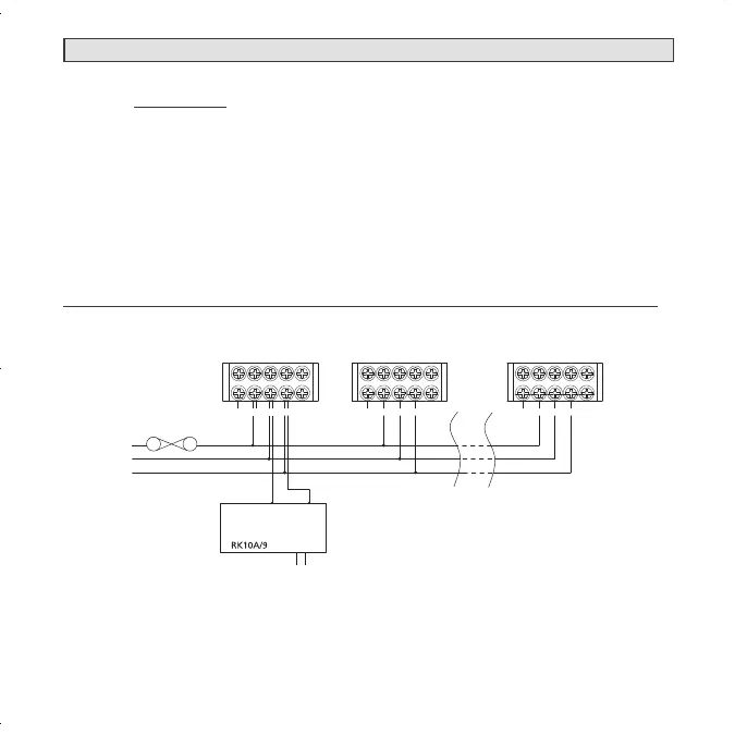
6.1.15 Terminals at back of mounting base are marked and coloured as follows:
MARKINGS
(Yellow) 9V 9Vdc POSITIVE POWER SOURCE
(Red) A ACTIVE
(White) SW SWITCH WIRE (FOR INTERCONNECTION ONLY)
(Blue) N NEUTRAL
(Orange) LOOP DEAD TERMINAL
WARNING: Connecting the Switch wire terminal to any other supply conduc-
tor may result in damage to the alarm, failure to operate or shock hazard and
void the warranty of the alarm.
EXAMPLE OF MULTIPLE ALARM WIRING / ISOLATION UNIT WIRING
6. INSTALLATION
LOOP
1
N
9V
SW
A
LOOP
2
SW
9V
A
N
BLUE
ORANGE
ORANGE
YELLOW
WHITE
RED
YELLOW
BLUE
WHITE
RED
24
9V
A
SW
N
LOOP
MAXIMUM OF 24 SMOKE ALMARMS
CONNECTION TO A
SW
N
FUSE ON
CIRCUIT
BREAKER
SEE INSTALLATION INSTRUCTIONS
FOR LIFSAVER RK10A/9 RELAY MODULE
TO ALARM PANEL
OR
AUXILIARY DEVICES
 Loading...