Install the Dimmers
Carefully follow the instrucons in this secon in
order to install the In-line dimmer. Please remember
that live electricity is dangerous. Do not take any
risks. If in any doubt, consult a qualied professional.
For other advice, please contact our dedicated
technical support team on 0121 250 3625.
1
Link the In-line Dimmer
2
The easiest way to learn how to install
Lightwave devices is to watch our short
installaon video which are accessible at
Turn o the mains power supply to your exisng power
circuit at the consumer unit.
1.1 Turn o the mains electricity supply
The In-line dimmer is a class 0 device which means that it should
be housed in a suitable dry locaon or electrical housing to
minimise the risk of contact with live electrical wires. If in doubt,
consult an electrician.
1.2 Prepare a suitable locaon
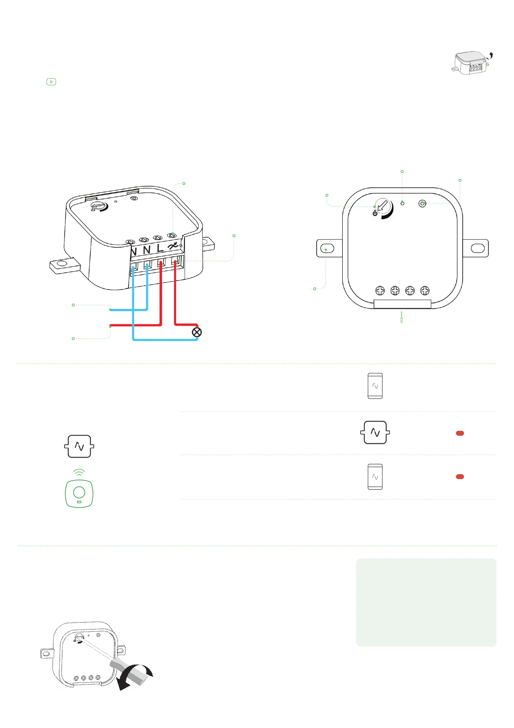
Remove the cover from the Lightwave
In-line Dimmer by carefully inserng a
screwdriver into the small slot located at
the boom edge.
1.3 Remove the faceplate
Carefully wire the Dimmer as shown in the diagram. Be aware
that exisng cables can vary in colour and may not always be
correctly labelled. If in any doubt, always consult a qualied
electrician. Replace the faceplate by hooking it onto the top edge
of the Dimmer and clipping in the boom.
1.4 Wire the Dimmer
To be able to command the dimmer, you
will need to link it to a Lightwave Link,
Link Plus or other Lightwave controller.
Please follow the in App instrucons which will explain
how to link devices.
On the In-line Dimmer, press and hold the ‘on’ / ‘o’ buon unl
the indicator LED ashes, and then release it. The Dimmer is now in
linking mode.
Using a Lightwave controller or the App, press the buon to link to
the device (the App instrucons will guide you through this). The
indicator on the Dimmer will ash to conrm that it is now linked.
Repeat the same process to unlink the device.
Other dimmer
funcons
3
Clearing the memory
To clear the memory, enter linking mode, and then hold down the
on/o buon unl the LED ashes. Release the buon and tap
(don’t hold) it. The LED will ash red to conrm that the memory
has been cleared.
Adjusng the dim range
The dim range adjuster can be used to decrease the dimming
range of the In-line Dimmer in order to achieve the maximum
compability with dimmable LED lamps. If a dimmable LED ick-
ers when it is dimmed, the range can be reduced incrementally
using the adjuster dial (as shown) and the LED re-tested. Keep
narrowing the dim range using the dial unl stability has been
achieved at all dim levels for that parcular LED lamp.
Dim range adjuster this can be
used to decrease the dim range
in order to achieve the maximum
compability with dimmable LED
lamps (see secon below)
Wiring terminal
Lamp
Neutral wire connecon
This wire is usually blue or
black in colour.
hps://support.lightwaverf.com
On/o buon
Press to turn on/o or
to link the device
LED indicator light
Screwdriver slot
Insert screwdriver
to remove the cover
plate.
Live wire connecon
This wire is usually brown
or red in colour.
Tightening screw
Mounng
bracket
GETTING STARTED
Press buon
on app
Hold buon on
dimmer
Visit www.lightwaverf.com to discover the latest
product updates and nd out what else you can do
with Lightwave products.
You can also sign up to our newsleer or keep up to
date with the latest updates and releases via Twier
and Facebook.
Follow Lightwave
ash
ash
 Loading...