Do you have a question about the Lincoln Electric LT-7 and is the answer not in the manual?
Specific warnings regarding California Proposition 65.
Safety guidelines for operating equipment with engines.
Warnings and precautions regarding Electric and Magnetic Fields (EMF).
Critical safety information about the dangers of electric shock.
Safety measures to protect against arc rays and sparks.
Precautions for handling welding fumes and gases.
Safety measures to prevent fires and explosions from welding sparks.
Precautions for handling compressed gas cylinders.
Safety guidelines for electrically powered equipment.
Information on electromagnetic compatibility and interference.
Techniques for minimizing electromagnetic emissions.
Guidelines for routine maintenance of welding equipment.
Technical specifications of the LT-7 Tractor.
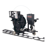
An overview of the LT-7 Tractor's features and capabilities.
Physical characteristics and build of the LT-7 Tractor.
Key attributes and functionalities of the LT-7 Tractor.
Guidance on suitable welding processes and required equipment.
Specific welding processes recommended for the LT-7 Tractor.
Constraints and limitations on welding processes for the LT-7 Tractor.
Compatible power sources for the LT-7 Tractor.
Necessary equipment for operating the LT-7 Tractor.
Details and part numbers for various cables.
Information on different contact nozzle assemblies.
Recommended optional accessories for the LT-7 Tractor.
Identification of LT-7 Tractor parts and components.
Key components related to the tractor's movement and steering.
Identification of components involved in wire feeding and control.
Overview and functions of the tractor's control box.
Components related to the front guidance system.
Components of the wire feed head assembly.
Description of the flux hopper assembly.
Procedures for mounting and adjusting the welding head.
General information pertaining to the assembly process.
List of necessary tools for assembly and setup.
Installation and operation of the K231-1 contact nozzle.
Details on K148 contact nozzle usage, installation, and maintenance.
Step-by-step instructions for installing the K148 nozzle.
Guidance on contact tip wear and replacement for K148 nozzle.
Installation of the K149 Linc-Fill extension for long stick-out.
Information on the water cooling attachment for tip life.
Procedures for mechanically setting up the tractor for different weld types.
Instructions for setting up the tractor for butt welds.
Setup procedures for specific butt weld configurations.
Various methods for steering and tracking the tractor.
Guidance on using the self-steering method.
Using the pointer assembly for weld alignment.
Installation and use of the K230 Butt Guide.
Setup for tracking using channels.
Setup for tracking using bars.
Instructions for setting up the tractor for horizontal fillet welds.
Setup of the front guidance assembly for horizontal fillets.
Procedures for mounting and adjusting the welding head for horizontal fillets.
Information on the K232 Fillet-Lap Guide Kit.
Step-by-step installation of the K232 Kit.
Procedures for aligning the tractor in the weld joint.
Instructions for setting up the tractor for lap welds.
Procedures for welding lap joints.
Instructions for setting up the tractor for flat fillet welds.
Information on the K229 Flat Fillet Kit.
Step-by-step installation of the K229 Kit.
Setup of the front guidance assembly for flat fillets.
Installation of the rear support wheel.
Mounting the reel and control box for Twinarc modifications.
Mounting the head for flat fillet welds.
Aligning the tractor in the joint for flat fillets.
Overview of the K395 Track Model LT-7.
Key features of the track model LT-7.
Steps to configure the K395 track model.
Procedures for setting up the tractor on-track.
Steps for configuring the rear wheels.
Steps for configuring the front frame.
Continuation of K395 track model configuration.
Procedures for setting up the tractor off-track.
Information on the K400 track conversion kit.
List of parts included in the K400 conversion kit.
Information about K396 track sections.
Details on Tiny Twinarc kits for submerged arc welding.
List of parts included in the K277 Tiny Twinarc kits.
Procedures for modifying the LT-7 for Twinarc welding.
Specific modifications to the wire feed head for Twinarc.
Steps for modifying the wire straightener.
Frame modifications for specific Twinarc weld types.
Steps for frame conversion for butt and horizontal fillet welds.
Specific modifications for butt welds using Twinarc.
Specific modifications for horizontal fillet welds using Twinarc.
Specific modifications for horizontal lap welds using Twinarc.
Frame modifications for 45° flat fillet welds with Twinarc.
Information on the K280 Vertical Head Lift Adjuster.
Steps for making electrical connections to the LT-7 Tractor.
Guidelines for selecting appropriate copper cable sizes.
Procedures for loading welding wire coils onto the reel.
Essential safety measures before operating the tractor.
Warnings about mechanical hazards during operation.
Understanding parts at electrode potential and maintaining clearance.
Basic guidelines for operating the LT-7 Tractor safely.
Overview of the LT-7 control box functions and controls.
General information regarding operation settings.
Explanation of Constant Current and Constant Voltage modes.
Details on operating in Constant Current mode.
Details on operating in Constant Voltage mode.
Procedure for selecting between CC and CV modes.
Instructions for selecting weld polarity (Positive/Negative).
Step-by-step guide to performing a weld with the LT-7 Tractor.
A general description of the LT-7 Tractor's capabilities.
Explanation of the LT-7's input power circuitry.
Explanation of the tractor's control and logic systems.
Technical explanation of the LT-7's travel circuit.
Technical explanation of the variable voltage circuit.
Explanation of how Silicon-Controlled Rectifier (SCR) circuitry controls speed.
General guidelines for routine maintenance.
Safety measures to be taken during maintenance.
Maintenance procedures for the wire feed head assembly.
Maintenance for the wire drive motor and gearbox.
Inspection and maintenance of drive rolls and guide tubes.
Inspection and maintenance of the wire straightener.
Maintenance of the contact nozzle assembly.
Procedures for mounting wire reels to prolong shaft life.
Basic maintenance for the control box.
Maintenance for the tractor's drive motor gearbox and clutch.
Information on circuit protection features and resetting breakers.
Explanation and reset procedure for the Grounding Lead Protector.
Instructions on how to effectively use the troubleshooting guide.
A comprehensive guide to diagnosing and resolving machine problems.
Procedures for troubleshooting PC board related issues.
Understanding the meaning of PC board status indicator lights.
Specific procedures for testing various components.
Procedure to test the functionality of the wire drive motor.
Procedure to test the functionality of the travel motor.
Steps for removing and replacing the wire drive motor.
Steps for removing and replacing the travel motor.
Procedure for calibrating the travel circuit.
Steps to retest the machine after repairs.
Common output issues and their troubleshooting steps.
Wiring diagram for models below Code 9100.
Wiring diagram for models above Code 9100.
Connection diagram for models below Code 9100.
Connection diagram for models above Code 9100.
Complete machine schematic for models below Code 9100.
Complete machine schematic for models above Code 9100.
Diagram of the control board assembly.
Diagram of the logic board assembly.
Schematic of the variable voltage board.
Diagram of the variable voltage board assembly.
Diagram of the travel board assembly.
| Brand | Lincoln Electric |
|---|---|
| Model | LT-7 |
| Category | Tractor |
| Language | English |