Do you have a question about the Lincoln industrial 94822 and is the answer not in the manual?
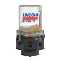
This document describes the Lincoln Industrial Models 94822 Chassis Lube Electric Grease Pump, Series "A," a key component in progressive-type centralized lubrication systems.
The Lincoln Industrial Models 94822 Chassis Lube Electric Grease Pump is an electrically operated pump designed for use in progressive centralized lubrication systems. Its primary function is to supply lubricant to various lubrication points via progressive metering devices. The pump incorporates a low-level sensor that triggers a blinking LED light on the circuit board when lubricant levels are low. This signal can also be sent to an optional dash-mounted light for remote indication.
The pump's lubrication cycles are controlled by an internal microprocessor. A proximity switch, installed on one of the system's secondary divider valves, is crucial for signaling the completion of a lubrication cycle. If this signal is not received within 30 minutes, a fault signal will be generated. This monitoring feature helps ensure proper pump operation and detects blocked or broken supply lines. The pump assembly consists of a pump housing, an electric gear motor, the microprocessor, and a plastic reservoir with a stirring paddle. Its high operating pressure capability allows it to supply lubricants up to NLGI #2 grease.
Mounting: The pump should be mounted vertically on an even surface using three bolts. It is important to select an easily accessible location that allows access to the timer and the lubricant reservoir filler fitting.
Filling the Reservoir: The reservoir is filled through a grease fitting located at its base. It can be filled using a hand-operated grease pump, a pneumatic pump, or an electronic transfer pump. Users must exercise caution when filling with pneumatic or electric transfer pumps to avoid bursting the reservoir. The reservoir should be refilled when the grease reaches the "MIN" mark and filled up to the "MAX" mark.
Priming the System:
Operational Test / Triggering an Additional Lubrication Cycle: An operational test can be performed to check the pump's function. If necessary, switch on the battery voltage and the driving switch. To check if power is applied to the printed circuit board, observe if the left-hand LED (1, Fig. 14) is lit. Press the pushbutton (> 2 seconds) to trigger an additional lubrication cycle until the right-hand LED (3) lights up. The right-hand LED indicates operating time, monitoring time (30 minutes in case of a fault), and faults. When an additional lubrication cycle is triggered, a shorter pause time occurs, followed by a normal lubrication cycle. Additional lubrication cycles can be triggered at any time.
Setting the Pause Time: The pause time, which determines the frequency of lubrication cycles, is adjustable. It can be set to 15 different settings using the blue rotary switch. To set the pause time, the cover on the pump housing must be removed. After setting, the cover should be screwed back on. The pause time starts and stops via the machine contact or ignition switch. If the setting is modified within the pause time, the printed circuit board adopts the new value only at the end of the operating time. The pause time should be adjusted according to the specific lubrication cycles.
Proximity Switch: A proximity switch (initiator) installed on a metering device monitors piston movements and signals the completion of the pump operating time. This ensures all pistons of the metering device have dispensed their lubricant quantity. The operating time depends on the system's lubricant requirement and the location of the proximity switch. During the operating time, the signal lamp is permanently lit.
Monitoring Time: A fixed monitoring time of maximum 30 minutes is implemented. Normally, the monitoring time ends concurrently with the operating time. If no switching-off signal is received from the proximity switch by the printed circuit board within 30 minutes, a fault signal will occur, indicated by the signal lamp flashing.
Functional Check: Each time the machine contact (external contact) or the driving switch is switched on, a functional check of the drive motor and signal lamp automatically takes place. During this check, the motor runs for 0.1 second (causing the stirring paddle to rotate slightly), and the signal lamp lights up for 2 seconds. If a fault is detected, the signal lamp flashes.
Fault Indication: The signal lamp or LED (Fig. 9) indicates the operating state of the centralized lubrication system and flashes with different frequencies to indicate faults.
Acknowledging and Remedying a Fault: When the pushbutton is pressed briefly (< 1 second), the fault is acknowledged, and the lamp stops flashing and remains permanently lit. Acknowledged faults are stored even after the driving switch or machine contact is switched off and will flash again upon switching on. To remedy a fault:
Troubleshooting:
| Brand | Lincoln industrial |
|---|---|
| Model | 94822 |
| Category | Water Pump |
| Language | English |