03/27/08 Page 5 of 7
LINE 6 CONFIDENTIAL
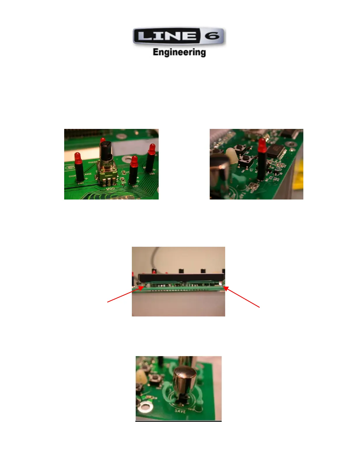
7. LED’S: All LED’s are to be mounted on the TOP SIDE of the PCBs
Through-hole LEDs (D100-105) should be mounted to the UI Middle PCB (35-00-0272-1) using Spacer
(30-15-0029-2).
Through-hole LED (D18) should be mounted to the UI Upper PCB (35-00-0272) using Spacer
(30-15-0029-3).
Through-hole LEDs (D106 D108 D110 D113) should be mounted flush to the UI Lower PCB
(35-00-0272-2). See Photos.
8. LCD (50-02-0240): LCD is to be installed flush to the User Interface Upper PCB (35-00-0272) using the
metal bracing points located on the right, left, and middle section of the LCD Top region. All of these bracing
points are to be seated flush to the User Interface Upper PCB (35-00-0272). See Photos.
9.
Installation of Buttons: Chrome plated Buttons (30-27-0300) are to be heat-staked at all Tact Switch
locations (SW1-4 SW8-13) on User Interface Upper PCB (35-00-0272). See Photo.
 Loading...