Do you have a question about the Linn Klimax 350 and is the answer not in the manual?
List of essential tools required for performing fault finding and component replacement procedures.
Overview of main procedures, referencing appendices for detailed removal and re-fitting steps.
Initiation point for the fault finding process, beginning with initial checks.
Procedure for checking for power surge, burnt components, or signs of over-driving the loudspeakers.
Determining if fault symptoms affect one or both loudspeakers to guide the next steps.
Testing by swapping speaker or signal cables to isolate the fault's location.
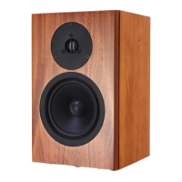
Identifying the specific part (3K Array, Amplifier Module, Bass Drivers) responsible for the fault symptoms.
Procedures for swapping components and contacting service if symptoms persist.
Verifying mains leads, signal cables, and checking for interference or system-wide issues.
Assessing if symptoms are identical on both speakers and swapping signal cables.
Testing other system devices and isolating suspect parts by following Section 1 procedures.
Safety precautions and preparation for handling equipment and disconnecting cables.
Step-by-step instructions for safely removing the 3K Array assembly from the speaker.
Detailed steps for correctly re-installing the 3K Array into the loudspeaker, ensuring proper alignment.
Safety guidelines, preparation, and advice for two-person handling of the amplifier module.
Procedure for disconnecting and removing the amplifier module, including cable management.
Instructions for correctly re-installing the amplifier module into the speaker cabinet, ensuring proper fit.
Guide for connecting speaker cables to the amplifier module in passive mode, ensuring correct connections.
Guide for connecting speaker cables to the amplifier module in aktiv mode, ensuring correct connections.
Steps to securely fasten the amplifier module back into the speaker cabinet, including bolt tightening.
Safety and preparation notes for servicing the upper servo bass drive unit, requiring two people.
Procedure for removing the 3K Array, grill, trim ring, and securing screws for the upper servo bass driver.
Steps for soldering wires and re-installing the upper servo bass drive unit, including torque specifications.
Safety and preparation for the lower servo bass drive unit replacement, advising two-person handling.
Procedure for removing the grill, trim ring, and securing screws for the lower servo bass driver.
Steps for connecting cables and re-installing the lower servo bass drive unit, including torque specifications.
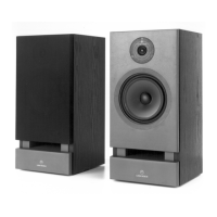
| Enclosure Type | Bass reflex |
|---|---|
| Operating Principle | Active |
| Connectivity | XLR |
| Tweeter | 25 mm |
| Midrange | 75 mm upper mid, 165 mm lower mid |