Rev: 10.04.18 Page 2 CCD-0002274
TI-284
KWIKEE
®
DOOR SWITCH STEP ACTIVATION
INSTALLATION GUIDE (1421330)
STEPS
Door Switch Installation
Lippert Components, Inc. (LCI) recommends that the switch be installed on the latch side of the door.
However, hinge-side installation is acceptable. Some experimentation with the switch position may be
necessary to achieve proper step operation. The Kwikee Step assembly should begin to extend when the
door is opened between one and four inches.
Removing Existing Switch
NOTE: No hardware is sold with a replacement door switch kit. Make sure to save existing hardware (i.e.
screws) for re-use. Use the double-sided adhesive tape that comes attached to the standard new
door switch for a temporary hold.
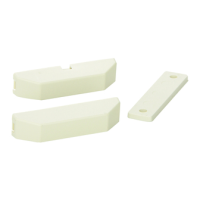
1. Remove the magnet contact from the screen door first.
A. Use a screwdriver or a cordless or electric drill with appropriate drill bits to remove the two screws
holding the magnet in place.
NOTE: Keep the two screws for use when installing the new magnet (Fig. 1).
B. If present, remove any remaining adhesive residue from the surface of the screen door. Use a
utility knife or plastic scraper to remove the residue as needed.
2. Remove the switch from the door frame.
A. Use a screwdriver or a cordless or electric drill with appropriate drill bits to remove the two screws
holding the switch in place.
NOTE: Keep the two screws for use when installing the new switch (Fig. 1).
B. If present, remove any remaining adhesive residue from the surface of the door frame. Use a utility
knife or plastic scraper to remove the residue as needed.
3. Disconnect the ground wire and the wire connected to the control box.
A. Follow the wires from the switch to the underside of the vehicle.
I. The ground wire will be attached to the vehicle with a ring terminal and self-tapping screw.
II. The other wire will be connected to the wire harness that connects to the control box that
operates the step.
B. Pull the existing wires down through the hole in the door frame to the underside of the vehicle.
C. To disconnect the ground, remove the screw holding the ring terminal and ground wire to the
vehicle.
D. Using wire cutters or similar tool, cut the brown wire to the switch at the 4-way connector just
behind the butt connector.
E. Strip back the wire connected to the 4-way connector approximately
½"
and attach a heat shrink
butt connector.
 Loading...