Rev: 10.04.18 Page 5 CCD-0002274
TI-284
KWIKEE
®
DOOR SWITCH STEP ACTIVATION
INSTALLATION GUIDE (1421330)
STEPS
TI-284
KWIKEE
®
DOOR SWITCH STEP ACTIVATION
INSTALLATION GUIDE (1421330)
STEPS
IMGL Control
(2006 and newer)
Pre-IMGL Control
(Before 2006)
Troubleshooting
The Kwikee Step assembly should begin to extend when the door is opened between one and four inches.
The step assembly should retract when the door is closed.
If, after installation of a new switch, the step does not operate properly, do as follows:
1. Check to make sure that there are no obstructions in the path of the step assembly preventing its
operation.
2. Check to make sure that all wiring connections are tight and secure.
Replacement Parts—General Information
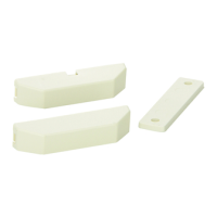
There are three types of door switches available:
• Rectangular switch (small and large sizes)
• Round switch (
¾
" or
⁄
" core)
• Plated plunger switch.
The replacement procedures outlined in this document apply to door switches used with any Kwikee
control unit - both the latest IMGL (integrated motor/gear box/ linkage) version (Kwikee 909510000 / LCI
379146) used on 2006 or newer models (Fig. 2) and earlier version control units (Fig. 3).
When selecting a replacement door switch from the enclosed guide, make sure to select one based on the
type of control unit that is present.
• For most older units using the pre-IMGL control unit (Fig. 3), select one of the white (normally closed) door
switch options. (Exceptions are noted in the Replacement Parts Guide section.)
• For units with the current IMGL control unit (Fig. 2), select one of the black (normally open) door switch
options. The IMGL-type control unit operates properly with any of the “Normally Open” switches. The IMGL-
type control unit will not operate properly with the white “Normally Closed” switches, the step will operate
backwards.
NOTE: No hardware is sold with a replacement door switch kit. Make sure to save existing hardware (i.e.
screws) for re-use. Use the double-sided adhesive tape that comes attached to the standard new
door switches for a temporary hold.
Fig. 2 Fig. 3
 Loading...