Rev: 06.01.23 Page 5 CCD-0007029
Fig. 3
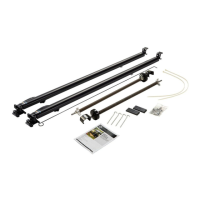
Assemble the Extension Rod and Cap
1. Slide the extension rod (Fig. 3A) into the idler head spring assembly end cap (Fig. 3B).
2. Fasten using the provided 1/4” - 20 x 5/8” slotted pan head, self-threading screw (Figs. 3C or 4A).
A
B
C
Fig. 4
A
3. Repeat steps 1 and 2 for the opposite end.
Installing the Solera Slide Topper Access Plate
NOTE: If the access plates are already pre-installed, part number 768004 (black) or 768005 (white) will not
be needed for this installation. Proceed to Installing the Solera Slide Topper Access Bracket section.
NOTE: The access plate (Fig. 5) can be mounted with the flat edge (Fig. 5A) at the top or bottom,
depending on which option allows for a more square installation on the unit.
1. Install the access plate below the T-molding (Fig. 6A) or on the T-molding (Fig. 6B).
A. If installing below the T-molding, start on one side of the front of the slide-out by placing one
of the two access brackets (Fig. 6A) against the bottom of the T-molding (Fig. 6B) making sure
the top corner of the slide-out (Fig. 6C) is as close to the corner as possible. Keep the mounting
bracket parallel with the side edge of the T-molding (Fig. 6D).
Fig. 5
A
Fig. 6
A
D
C
B
NOTE: There might be a slight gap between the T-molding side and the side of the mounting bracket (Fig. 6C)
if the corner does not have a 90 degree angle.

 Loading...