Rev: 07.06.21 Page 17 CCD-0003657
Note red dot on
or near one motor
terminal.
3/16" flag terminal,
fully insulated,
4 req'd.
DPDT reversing toggle switch,
Philmore #30 - 125.
1/4" spade terminal,
fully insulated,
4 req'd.
#10 insulated ring
terminal, 2 req'd.
6 Amp short stop breaker,
Bussman #121A06-A2M-HD.
Battery
Positive (+)
Battery
Ground ()
White Wire
Dark Blue Wire
Wiring Diagram
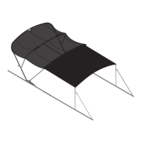
Operation
Fig. 24 Fig. 25
Before operating the power bimini top, thoroughly inspect the area around the entire bimini
assembly. Verify that nobody is in an area that will interfere with the motion of the bimini assembly.
Serious injury could result.
Helm-mounted Control Switch
Use the helm-mounted control switch to operate the power bimini top to verify successful installation.
1. If installed, remove the protective boot.
2. To extend the bimini top to full open position (Fig. 24), press and hold the helm switch until the
actuator motors turn off—do not release switch until both actuator motors turnoff.
3. To retract the bimini top to full down position (Fig. 25), press and hold the switch until motors turn
off—do not release switch until both actuator motors turnoff.
4. Install protective boot.
 Loading...