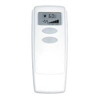
Fig. 4
LEARN
BUTTON
LIGHT
BUTTON
FAN
BUTTON
Fig. 1
19˚
20˚
and
Above
RECEIVER
HANGING
BRACKET
DOWNROD
CAUTION: FOR MOUNTING RECEIVER,CEILING
ANGLE SHALL NOT EXCEED 19 DEGREES
RECEIVER MODEL: CFR-3D
LITEX INDUSTRIES, LTD.
GRAND PRAIRIE, TX 75050
FOR CUSTOMER SERVICE CALL: 1-800-527-1292
Fig. 3
RECEIVER
CAUTION: DO NOT USE
FAN SPEED CONTROL
IN CANOPIES WHERE
THE MOUNTING IS NOT
AS SHOWN IN FIGURE 3
OF THE INSTALLATION
INSTRUCTIONS
GENERAL INFORMATION
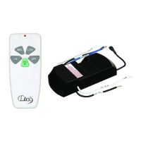
This remote control is designed to separately control your ceiling fan speed and light brightness.
There is one button to control the fan speed and another button to control the light brightness and off.
The blue LED lights on the transmitter will light up to indicate fan speed depending on the number of times the fan button is pressed.
INSTALLATION AND OPERATING INSTRUCTIONS
I. SAFETY PRECAUTIONS
A. WARNING: HIGH VOLTAGE! Household electrical power can cause serious injury or death. Disconnect source of electrical
power to the ceiling fan by removing fuse or switching off circuit breaker. Make sure all electrical connections comply with local codes,
ordinances, the National Electrical Code, and ANSI/NFPA 70-199. If you are unfamiliar with electrical wiring, please use a qualified
and licensed electrician.
B. WARNING: To reduce the risk of fire, electrical shock, or personal injury, wire connectors provided with the remote control
receiver are designed to accept only one 12 gauge house wire and no more than two lead wires from the receiver. If your
house wire is larger than 12 gauge or there is more than one house wire to connect to the two receiver wires, consult an
electrician for the proper size wire connectors to use.
C. CAUTION: TO REDUCE THE RISK OF FIRE OR ELECTRIC SHOCK, DO NOT USE THE FAN
WITH ANY SOLID STATE SPEED CONTROL DEVICE OR CONTROL FAN SPEED WITH A FULL
RANGE DIMMER SWITCH.
D.
Do not use this remote control with solid state ceiling fans.
Electrical source and fan must be 115/120 volts, 60 Hz.
Maximum fan motor amps: 1.25; Maximum light watts: 300 incandescent only.
II. INSTALLATION OF RECEIVER (Please refer to Figure 1 before continuing.)
A. Manually set fan speed control to HIGH via pull chain and set light to ON via pull chain.
IMPORTANT:
Fan speed and light control will not be activated by remote if pull chains for fan and light
are not set to the HIGH and ON positions, respectively.
B.
Disconnect source of electrical power to the ceiling fan by removing fuse or switching off circuit breaker.
C.
Lower ceiling fan canopy from the mounting bracket.
D.
Disconnect existing wiring between ceiling fan and supply at electrical outlet box.
E.
Lay the black antenna wire on top of the receiver and slide the
receiver into the mounting bracket (Figure 1).
F.
Using the wire connectors supplied, make wiring connections as follows
(Figure 2):
CONNECT: TO:
GREEN fan wire......................................................BARE supply wire
BLACK receiver wire (AC IN L)...............................BLACK supply wire
WHITE receiver wire (AC IN N)...............................WHITE supply wire
WHITE receiver wire (TO MOTOR N)......................WHITE fan wire
BLACK receiver wire (TO MOTOR L)......................BLACK fan wire
BLUE receiver wire (FOR LIGHT)............................BLUE light wire (from fan)
Wrap each wire connector separately with electrical tape as an extra safety measure.
If other fan or supply wires are different colors than those
mentioned, have this unit installed by a qualified electrician.
G. Push all connected wires up into outlet box. Make sure antenna rests outside of mounting bracket.
H.
Re-install the canopy on the mounting bracket.
III. AUTOMATED LEARNING PROCESS/ACTIVATING CODE
A. Remove battery cover and then remove plastic that is wrapped around battery.
B.
Install the 12-volt battery.
C.
Restore electrical power. Within 30 seconds of restoring electrical power, press the “LEARN” button in the battery compartment for 3 seconds or until fan
switches to MEDIUM speed. Test the light and fan functions to confirm the learning process is complete. (Figure 4)
CAUTION: The transmitter can be programmed to multiple receivers or fans. If this is not desired, turn power off to any other programmable receiver or fan.
D.
Locate dimmer switch to the left of the “Learn” button in the battery compartment. (Figure 4) Set dimmer switch to the “ON” (D) position only if using
incandescent bulbs. Set dimmer switch to “OFF” (O) position if using compact fluorescent bulbs.
NOTE: Compact fluorescent bulbs are NOT compatible for use with dimmer controls.
E.
Replace battery cover on transmitter. (Figure 4)
IV. TRANSMITTER--CARE AND OPERATION
A. Store the transmitter away from excess heat or humidity.
B.
To prevent damage to transmitter, remove the battery if not used for long periods.
C.
Operation buttons on the front panel of the transmitter:
button -- used to control FAN speed. Each time the button is
pressed, the blue LED lights will cycle through each fan speed and light up
to indicate the speed as follows:
3 LED lights on fan HI speed
2 LED lights on fan MED speed
1 LED light on fan LOW speed
No LED lights on fan OFF
button -- for LIGHT brightness and off. The light function is controlled by
pressing the button. Hold button down to increase or decrease light. Tap
button quickly to turn light off or on. If you press the button in excess of 0.7 seconds
it becomes a dimmer. The light varies cyclically in 0.8 seconds.The light button has auto
resume, so the light will stay at the same brightness as the last time it was turned off.
IMPORTANT: Make sure that fan has been turned off at wall switch and then allow blades to
come to a complete stop before manually activating the reverse switch on the fan.
V. TROUBLESHOOTING GUIDE
A. Fails to operate:
1. Power to the receiver?
2. Receiver wired correctly?
3. Manual speed control on fan in highest position?
4. Light kit switch turned on?
5. Good battery in the transmitter?
6. Learning process between fan and transmitter may not have been successful. Turn power off,
remove battery cover and repeat Steps C and D in Part III (Automated Learning Code) above.
B.
Won't operate at distance: If transmitter operates fan and light kit when up close, but not at 40 feet
away, try placing the black antenna wire higher and make sure the black antenna wire is visible.
12V
Size A23
MODEL: RCI-107L
CAUTION:
TO REDUCE THE RISK OF FIRE OR ELECTRIC SHOCK, DO NOT
USE THE FAN WITH ANY SOLID STATE SPEED CONTROL DEVICE
OR CONTROL FAN SPEED WITH A FULL RANGE DIMMER SWITCH.
TRANSMITTER
(front)
(back)
Fig. 2
AC SUPPLY
BLACK
WHITE
BARE GREEN
BLACK
WHITE
BLUE BLUE
BLACK
WHITE
ANTENNA
AC SUPPLY
BLACK
WHITE
L
D
O
DIMMER
SWITCH
PATENT PENDING