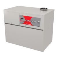
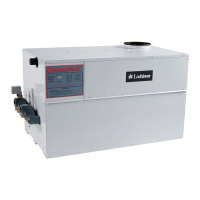
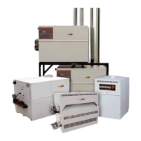
Do you have a question about the Lochinvar COPPER-FIN 497 - 2067 and is the answer not in the manual?
Important notices and warnings before starting installation or operation.
Procedures for inspecting the unit upon delivery for damage or shortages.
Explains warranty limitations related to installation and operation.
Critical safety alerts and precautions for the user.
Lists installation standards and local code requirements.
Guidance on selecting an appropriate installation site for the unit.
Specifies minimum space requirements around the unit for operation and service.
Methods to prevent freezing damage to the unit and system.
Specific requirements for installing units outdoors.
Procedures for safely winterizing the unit.
Requirements for air supply to ensure proper combustion and venting.
Maintenance and function of the combustion air filter.
Various methods for supplying combustion air to the unit.
General rules and safety precautions for venting systems.
Guidelines for properly supporting vent pipes to prevent sagging.
Specifies required distances for vertical vent outlets from structures.
Preferred placement for optimal performance of the barometric damper.
Details on this specific venting method using rooftop termination.
Procedures and considerations for using masonry chimneys.
How to check chimney suitability for appliance venting.
Details on venting requirements for outdoor unit installations.
How to safely connect the unit to the gas source.
Requirements for gas pipe sizing and installation according to codes.
Explanation of the gas delivery system and its control components.
Description and function of the unit's combination gas valves.
Procedure to verify gas supply pressure meets specifications.
How to adjust manifold pressure for proper burner operation.
How to connect water lines to the unit's inlet and outlet.
Installation and purpose of the pressure relief valve.
Function and requirements of the water flow switch.
Description of the low water cutoff safety feature.
General plumbing guidelines for boiler system installations.
Requirements for selecting an appropriate circulating pump.
How the pump operates during heating cycles.
Details on the pump's delay feature for residual heat removal.
Importance of maintaining minimum water temperatures to prevent condensation.
Impact of low system water volume on boiler efficiency and component life.
Managing low return water temperatures to prevent condensation.
Specific considerations for these types of heating systems.
Considerations for applying the unit in chilled water systems.
General plumbing practices and rules for boiler system installations.
When and how to install a boiler bypass for flow control.
Description of the gauge and its function for monitoring system status.
Step-by-step process for filling the system with water and purging air.
Importance of water treatment, especially in hard water areas.
How to safely connect the unit to the electrical power supply.
Various ways to connect external controls and safety devices.
How to set and adjust the unit's temperature controls.
Details on setting specific temperature parameters like setpoint and differential.
How to use the outdoor reset control for efficient operation.
Types and functions of temperature sensors used in the unit.
Connecting a remote sensor for accurate pump delay operation.
How to install sensors for accurate readings and reliable operation.
Components and function of the hot surface ignition system.
Understanding the status LED codes on the ignition module.
Nominal timings for ignition sequences and control operations.
Interpreting the unit's operational lights and diagnostic codes.
Step-by-step instructions for safely starting the appliance.
Procedure for safely shutting off the gas supply to the unit.
Verifying water quality and freeze protection fluid status.
Procedure for filling the system with water and testing for leaks.
Removing air from the water system for proper operation.
Procedure to detect and address potential gas leaks before operation.
Inspecting the integrity of vent and air piping for safety.
Performing operational checks before initial use of the boiler.
Determining the necessary temperature increase for domestic hot water.
Managing water speed for optimal heat exchanger performance and longevity.
Setting initial water flow rates during setup.
Minimum pipe sizes for common manifold piping to ensure adequate flow.
Requirements and installation of the circulating pump for water heaters.
Description and function of the unit's sophisticated heat exchanger.
Adjusting water heater temperature for optimal performance and safety.
Proper connection of cold water supply to prevent condensation issues.
Setting and function of the high limit control for safety.
Information on optional pressure relief valves and their installation.
Managing thermal expansion in closed hot water systems.
Preventing issues related to hydrogen gas buildup in unused systems.
Keeping the area around the unit clear of obstructions and flammables.
Maintenance schedule and procedure for the circulating pump.
How to check and interpret burner flame patterns for proper operation.
Steps for cleaning flue passages to maintain efficiency and safety.
Procedures for cleaning the heat exchanger to remove soot and debris.
Ensuring proper air supply for combustion and ventilation.
Steps to verify the ignition system is functioning correctly.
Step-by-step process detailing the unit's operational sequence.
Electrical power requirements and connection details for the unit.
The control unit responsible for managing ignition sequences.
The main control unit that maintains desired temperature set points.
The process of clearing the combustion chamber of by-products after operation.
The function that keeps the pump running after burner shutdown to remove residual heat.
Schematic showing electrical connections and operational logic flow.
Visual representation of component wiring and connections for troubleshooting.
| Brand | Lochinvar |
|---|---|
| Model | COPPER-FIN 497 - 2067 |
| Category | Water Heater |
| Language | English |


 Loading...