17
7000INST Copyright Lockmasters, Inc. 5/25/11
Step 17 – Use of Filler Blocks
Step 17A – Insert the applicable ller block into the inside base plate before installation.
Option 1 – If you are not utilizing Access Control or monitoring the bolt sensors, push
the wire into the inside base plate. Insert the SOLID ller block (O).
Option 2 – If using external conduit on the secure side of the door, insert the NOTCHED
Filler Block (O). Feed the Access Control & Bolt Sensors Wiring through the conduit
and make connections (See Wiring diagram on page 19).
NOTE: Position the conduit snuggly against the notched ller block. DO NOT insert
conduit directly into the inside base plate. It will interfere with bolt retraction.
Option 3 – If the door is prepped with an internal raceway and the optional F, wire entry
hole has been drilled use the Wire Routing Box (D) to conceal the Access Control &
Bolt Sensors Wiring. As it needs to be routed outside of the inside base plate in order
to enter the raceway.
LKM7000 Installation
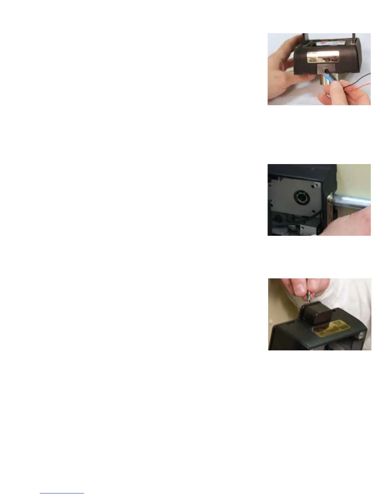
17a - Inserting the correct ller block into the IBP.
This installation used external conduit so the
notched ller block was needed - as described in
Option 2.
Correct position of the conduit against IBP.
Option 3 - Internal raceway option.
 Loading...