Do you have a question about the Loctite UVALOC 1000 and is the answer not in the manual?
Explains warning and caution signal words and their implications.
Lists the components included with the UVALOC 1000 unit.
Provides critical safety instructions and warnings for safe operation.
Details general operating guidelines, ozone production, and special label explanations.
Covers lamp life, bulb handling, overheating, and repair/servicing precautions.
Defines the intended use, prohibited applications, and system description.
Explains the system's function, radiation principles, and UV minimum settings.
Details UV spectrum ranges (UVA, UVB, UVC) and shows bulb output graphs.
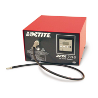
Identifies and describes front panel controls, display, and connections of the controller.
Details rear panel connectors, fuse, and power supply information for the controller.
Identifies and describes front panel components of the lamp housing, like ventilation slots.
Details rear panel connections, compressed air supply, and fan for the lamp housing.
Describes internal lamp housing components like the reflector, UV bulb, and cooling channel.
Describes the cure chamber's rack levels, perforated plate, and door safety switch.
Provides detailed dimensional drawings and specifications for the tunnel version.
Specifies necessary clearance and safety areas around the unit for proper ventilation and maintenance.
Outlines requirements for a dry, well-ventilated installation site.
Details the steps for connecting power, pneumatic hose, foot switch, and data cables.
Provides instructions and safety precautions for installing a new UV bulb.
Guides through the initial power-on, bulb warm-up, and readiness indication.
Explains the procedure for selecting the user interface display language.
Describes how to set exposure time and select continuous mode operation.
Details how to adjust exposure time settings and select operating modes.
Explains how to change the power output setting between 500 W and 1000 W.
Details the procedure to reset lamp operating hours and ignition count.
Describes the process for calibrating UV output measurements using the 'UV Adjust' menu.
Explains how to set the minimum acceptable UV output threshold via the 'UV Minimum' menu.
Provides guidance on placing parts in the chamber and shows radiation intensity levels per rack.
Details how to initiate an UV exposure cycle using foot switch or external signal.
Explains the correct procedure for shutting down the unit via the 'Turn off' menu.
Warns against improper shutdown via power switch, emphasizing controlled cooling.
Describes how to activate the emergency stop and the steps to return to normal operation.
Refers to section 4.5 for the procedure to start the unit with a cold bulb.
Provides steps for starting the unit when the bulb is already at operating temperature.
Explains the temperature sensor, error messages, and how the system protects against overheating.
Describes the door safety switch that prevents opening during exposure cycles.
Details the UV sensor for monitoring intensity and setting UV minimum values.
Provides information on unit disposal and compliance with local regulations.
Warns about mercury content in the bulb and specifies hazardous waste disposal.
Lists error messages, their causes, and corrective actions for common issues.
Troubleshoots error messages related to hardware failures and suggests contacting service.
Addresses errors for inadmissible UV levels and potential causes like sensor contamination.
Troubleshoots shutter operation errors related to compressed air supply or jammed shutters.
Explains errors regarding inadmissible lamp voltage and potential power supply issues.
Troubleshoots errors where the lamp fails to ignite, possibly due to overheating or no bulb.
Addresses errors indicating a missing or disconnected lamp voltage cable.
Troubleshoots errors related to the data cable connection between lamp housing and controller.
Troubleshoots shutter opening failures potentially caused by lack of compressed air.
Addresses warnings when UV output drops below the set minimum threshold.
Explains reasons for premature cancellation of exposure cycles, excluding emergency stop.
Provides a table of common malfunctions, their possible causes, and corrective actions.
Provides detailed instructions and safety precautions for replacing the UV bulb.
Details the procedure for replacing the filter pad, including disassembly steps.
Guides through the process of replacing the UV sensor and its associated PCB.
Provides steps for disconnecting and replacing the sensor cable.
Details the procedure for removing and replacing the unit's reflector.
Lists available spare parts, accessories, their Loctite types, and order numbers.
Illustrates pin connections for the footswitch (XS1) and controller interfaces.
Details the pin connections for the XS2 PLC interface for external control systems.
Presents the manufacturer's declaration of conformity with EC regulations and standards.
| Brand | Loctite |
|---|---|
| Model | UVALOC 1000 |
| Category | Power Tool |
| Language | English |