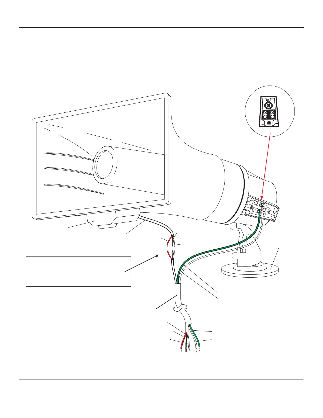
WIRING DIAGRAM OF MODEL TLO OUTDOOR SPEAKER/MICROPHONE
POSITIONING TLO
After TLO has been mounted to desired structure (wall, pole, etc.), horn should be tilted in a downward position.
This will protect the microphone element from water damage.
See page 5
for connection diagram
1
2
1
2
3 5
6
7
RED
(12Vdc)
BLACK
(audio output)
BARE
(ground)
MOUNTING
ARM
WEST PENN 356
MICROPHONE
CONNECTION
{
Microphone connection
using three wire nuts
Red wire to red = 12Vdc
Black wire to black = Audio Output
Bare wire to bare = Ground
(C) BARE
(A) RED
(B) BLACK
To
Louroe AOP-SP70
Audio Conversion Unit
Green = speaker (positive)
White = speaker (negative)
Speaker terminal screws
green wire to #1 (positive)
white wire to #2 (ground)
Speaker Connections
green - positive
white - ground
1
2
MICROPHONE
CABLE
MICROPHONE PC BOARD
AND HOUSING
INSTALLATION AND OPERATING INSTRUCTIONS
Page 3 of 8
LOUROE ELECTRONICS® 6 9 5 5 VA L J E A N AVENUE, VAN NUYS, CA 91406 TEL (818) 994-6498 FAX 994-6458
website: www.louroe.com e-mail: sales@louroe.com
(818)
aopsp70_ inst_3/15