Do you have a question about the Lowrey Jamboree M325 and is the answer not in the manual?
Explains tone generation, vibrato, vibrato effects, and glide circuits.
Details upper keyboard keying, sustain, and preset control mechanisms.
Explains preset latching, activation, cancellation, and upper cancel.
Describes the function of flute filters and associated circuitry.
Covers flute collector amps, tremolo photocell, FET switchers, and volume controls.
Explains the flute mixing preamp and main/chorus enable switchers.
Details lower keyboard keying, R/S quality control, modulator, and volume switchers.
Explains Magic Genie Chords, minor/7th enable, and A2 scan disable functions.
Details arpeggio and strum keying functions and volume controls.
Explains Genie Bass, Root/Fifth Bass, and their respective controls.
Describes bass pedal functions, pedal cancel trigger, and bass keying.
Explains bass keying (rhythm on/off) and Boogie Woogie Bass operation.
Details Boogie Bass enable, reset, and trigger circuitry.
Explains rhythm clock, instrumentation, rhythm generators, and noise generator.
Covers snare, brush, and cymbal keyer/voicing circuits and their controls.
Explains rhythm control logic, modulation, and strum clock inversion.
Details AOC data flow, shift registers, and decoder logic.
Explains chorus modulation, bucket brigades, and VCO frequency control.
Describes the power supply voltage regulation and amplifier signal path.
Describes how to adjust the vibrato speed for optimal performance.
Details the procedure for tuning the organ's tone generator coils.
Explains how to eliminate DC transients (thumps) in percussion voices.
Describes how to minimize DC transients in lower keyboard voices.
Details tuning the Magic Chord Tuning Coil for proper chord output.
Explains how to match chord volume with Magic Chord tab on/off.
Regulates AOC decoder voltage supply for correct chord output.
Describes how to adjust DC offset voltage for bucket brigades.
Details the procedure for setting the amplifier bias current.
Explains how to use an oscilloscope for troubleshooting electronic organs.
Covers direct (DC) and decoupled (AC) input coupling for oscilloscopes.
Step-by-step guide to calibrate an oscilloscope for accurate measurements.
Explains how the time base controls sweep and determines waveform frequency.
Explains internal and external triggering for observing waveforms.
Provides notes on numbering, component references, and schematic layout.
Notes on VOM measurements, oscilloscope approximations, and switch positions.
Details resistor/capacitor tolerances and part number references.
| Manufacturer | Lowrey |
|---|---|
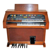
| Model | Jamboree M325 |
| Number of Keys | 44 |
| Pedalboard | 13-note |
| Power Supply | AC |
| Voices | 8 |
| Rhythms | 8 |
| Amplifier | Built-in |
| Speakers | Built-in |
| Year Introduced | 1970s |
| Features | built-in speakers |