High ATV, EPA (throttle travel) - maximum
Low ATV, EPA, ATL (brake travel) - maximum
EXP, EXPO (exponential) - start with 0
SUB trim (neutral trim) - centre
TH trim, coast brake - centre
Throttle reverse (servo reverse) - any setting; must not be changed after
completion of set-up procedure.
TRANSMITTER SETTINGS:
Asymmetrical stick travel is possible (2/3 throttle - 1/3 brake)
If your transmitter does not feature these set-up functions, it is already in “basic set-up” mode.
AUTOMATIC START CIRCUIT:
The IPC-V7.1 automatic start circuit gives you a crucial advantage at the start of a race. In this mode the response time of
the speed control is shortened (half-throttle on the transmitter corresponds to full-throttle on the speed control) and the set
current limiting value is doubled for the start of the race. The first time you reduce throttle (first turn) the IPC-V7.1
automatically reverts to the normal racing program.
• Activating the automatic start circuit:
with your vehicle in the start position, hold the brake on for at least five seconds (count up to 10); next time you open
the throttle the automatic start circuit is activated - but only once. You need to re-activate it for each new start.
CHECKING THE FUNCTIONS
If you run through the following functions with the throttle stick, you can check on the LEDs that
everything is set up correctly.
• Ensure that the speed control is not connected to the drive battery, and is switched off.
• Remove the motor pinion, or ensure in some other way that the wheels of the model are free to rotate.
• Switch the transmitter on.
• Set the transmitter throttle stick to neutral.
• Connect the speed control to the battery and switch the unit on.
• Hold the Set-up button pressed in for at least three seconds using the plastic screwdriver supplied.
SET-UP PROCEDURE
Set up the following basic functions on your transmitter (if present):
In set-up mode the IPC-V7.1 stores every step when you press the Set-up button. All the settings are stored
in the unit even when the speed control is subsequently disconnected from the battery.
Start with the transmitter set-up procedure:
• The bottom Set-up LED starts to flash green to indicate that you have selected set-up mode.
It continues to flash until the set-up process is completed.
• Leave the throttle stick at the neutral position and press the Set-up button once.
• The neutral position is now stored, the top Control LED flashes green, and the motor beeps.
• Move the transmitter throttle stick to the full-throttle position and hold it there, then press the Set-up
button once.
• The full-throttle position is now stored, and the top Control LED flashes red.
• Move the transmitter throttle stick to the full brake position and press the Set-up button once.
• The brake position is now stored, and the top Control LED and the bottom Set-up LED both glow red.
• The set-up process is complete, and your IPC-SR is ready to use.
• If you make a mistake during the set-up procedure, don’t worry: disconnect the battery for
about 10 seconds and start again from the first step.
• At the end of each run disconnect the drive battery, and only then switch off the transmitter.
At the start of each run switch on the transmitter first, then connect the drive battery.
FUNCTION STATUS BOTTOM SET-UP LED TOP CONTROL LED
Neutral and normal brake red off
Neutral and automatic brake off red
Forward part-load off green
Forward full-throttle red green
Brake part-load off red
Brake full-brake red red
BRAKE:
You should adjust the brake to meet the requirements of the track and racing conditions.
Normal brake: standard characteristics (for normal to slippery conditions): rotate the brake adjustor pot fully left.
This produces linear braking effect over the full stick travel, and provides perfect vehicle control during braking.
Soft brake (for extremely slippery surfaces): rotate the pot fully to the left. If you find you still want a reduction in
braking power, use the LOW ATV, EPA or ATL function (reduced brake travel) on your transmitter to reduce the effect.
Aggressive „hand-brake“: turn the brake pot to the right. This allows you to control your vehicle aggressively and throw
it round corners. Turn the pot towards the right-hand stop and the brake becomes more aggressive; turn it to the left and
it becomes more gentle. Note that maximum braking power is unchanged regardless of the position of the pot. If you wish
to adjust overall braking power you should reduce the travel of the brake function on your transmitter.
Automatic brake: as soon as you move the throttle stick to neutral, the speed control brakes automatically to allow you
to negotiate even tighter turns. You can adjust the power of the automatic brake at neutral to any setting within the range
1% (brake pot fully left) and 60 % (brake pot fully right). Of course, when you deliberately operate the brake from the
transmitter, full 100 % braking power is available again.
Switching brake programs: applies when you change from normal to automatic brake and vice versa: switch speed
control off --> press Set-up button and hold --> switch speed control on (with Set-up button pressed in!). You can tell
which brake program is in use by the status of the LEDs (see CHECKING THE FUNCTIONS).
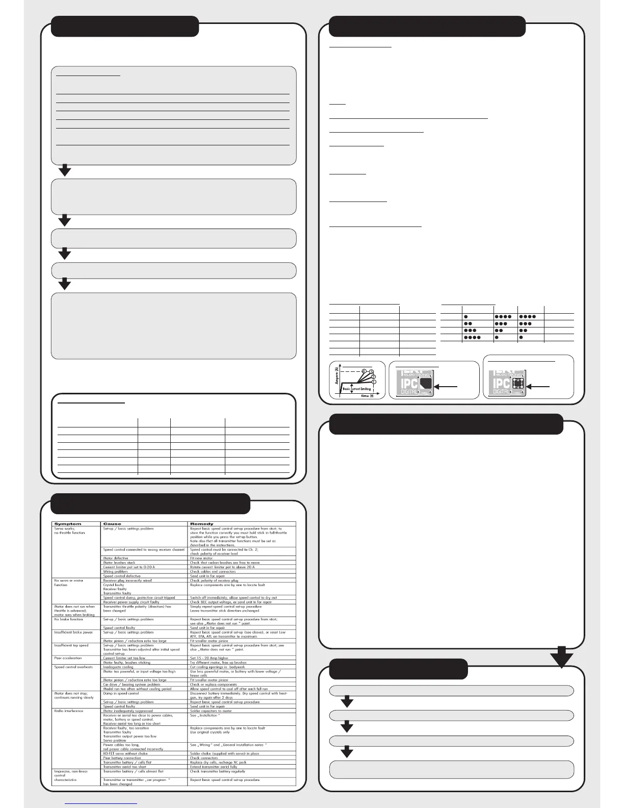
POWER PROGRAMS / CURRENT LIMITING:
The IPC-V7.1 can be adjusted to meet the exact requirements of your model and the track. To activate current limiting you
must install one of the plug-in chips (supplied in the values 30A, 50A, 65A, 80A and 120A) or the infinitely variable limiter
pot (accessory, No. 8110). Without one of the chips or the limiter pot fitted, maximum power is always available and
current limiting is not in force.
• The orientation of the plug-in unit determines the power program which is activated (see illustration). As soon as you
open the throttle, the basic current limiting value (value on the chip) is in force, and after a defined period of acceler-
ation (selected with the power program) the speed control intelligently increases the maximum current, and repeats
the process every time you resume acceleration.
• The various programs represent a method of fine-tuning the speed control’s response. The IPC-V7.1 always provides
a linear regulatory characteristic curve and superior battery efficiency, regardless of the program you choose.
PROGRAM ACCELERATION DRIVABILITY
BATTERY EFFICIENCY
1 VERY GENTLE
2 GENTLE
3 POWER + EFFICIENCY
4 MAX. POWER
RACING CLASS CURRENT LIMITER POWER PROGRAM
2-WD, 6-cell 65 A 3
Truck, 6-cell 80 A 3
4-WD, 6-cell 80 A 3
Pro 10 on-road 65 A 3
1:12 50 A 2
Touring car 65 A 3
Start with the following settings:
Programming with chips:
Programming with current limiting pot:
Current limiter programs:
example :
Chip 65 Ampere
power program No. 3
(accessory, No. 8110) The pot also provides 4 program
settings plus variable
current limiting within the
range 0 - 100 Ampere
65
Power programs:
In case of problems first check the trouble shooting guide or contact your hobby shop or LRP-importer. In
case of damage, repair fees are normally far below the recommended retail price of a new unit. Hobby
shops are not authorized to replace speed controls thought to be defective.
Warranty can only be accepted if it is claimed by the customer on the warranty sheet and the control sheet
and the original sales receipt are included.
For quick repair and return we definitely need your address, detailed description of the malfunction and the
original sales receipt. Repair may be refused without sales receipt.
To guarantee a proper repair, cut off or worn receiver plugs, wires and switches will be replaced and
charged in any case. Any speed control treated severely with silicone or anything similar inside, might not
be repairable.
Speed controls sent in for repair that operate perfect normally will be charged with a service fee. Therefor
first check with the trouble shooting guide.
LRP guarantees this speed control to be free from defects in materials or workmanship for 90 days from the
original date of purchase verified by sales receipt.
This warranty doesn’t cover: suitability for specific operation, incorrect installation, components worn by
use, application of reverse or improper voltage, shipping, tampering, misuse like any soldering inside the
unit, poor installation, replacing of wires on the board, connection to electrical components not mentioned
in the instructions, mechanical damage, immersion of water and cutting off the original wires, plugs,
connectors and switches.
Our warranty liability shall be limited to repairing the unit to our original specifications. Because we have no
control over the installation or use of this product, in no case shall our liability exceed the original cost of
this unit. We can't accept any liability for any damage resulting from using this product. By the act of
installing or operation this speed control, the user accepts all resulting liability.
REPAIR PROCEDURES/WARRANTY
DESCRIPTION OF FEATURES
TROUBLE-SHOOTING GUIDE
WHAT SHALL I DO?
• Send parcel to your national distributor.
• Distributor repairs/replaces the Speed Control.
• Shipment back to you usually by COD /cash on delivery), but is suject to your distributers
general policy.
• Package your Speed-Control carefully.
 Loading...