7. Function list
7-9
SV-iC5
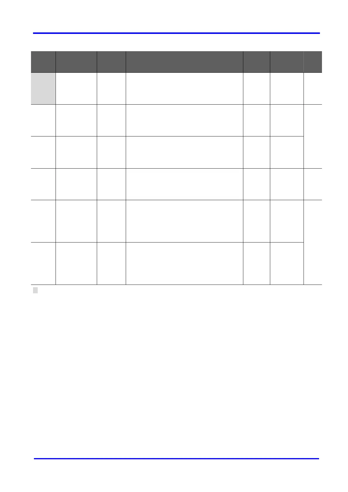
Function group 2
LED
display
Parameter
name
Min/Max
range
Description
Factory
defaults
Adjustable
during run
Page
H16 [Skip
frequency high
limit 3]
35.0 X
H17 S-Curve
accel/decel
start side
1/100 [%]
Set the speed reference value to form a curve
at the start during accel/decel. If it is set higher,
linear zone gets smaller.
40 X 9-13
H18 S-Curve
accel/decel
end side
1/100 [%]
Set the speed reference value to form a curve
at the end during accel/decel. If it is set higher,
linear zone gets smaller.
40 X
H19 [Output phase
loss protection
select]
0/1 Inverter turns off the output when the
phase of the inverter output (U, V, W) is not
properly connected.
0 O 12-5
H20 [Power On
Start select]
0/1 This parameter is activated when drv is set
to 1 or 2 (Run/Stop via Control terminal).
Motor starts acceleration after AC power
is applied while FX or RX terminal is ON.
0 O 9-9
H21 [Restart after
fault reset]
0/1 This parameter is active when drv is set to
1 or 2 (Run/Stop via Control terminal).
Motor accelerates after the fault condition
is reset while the FX or RX terminal is ON.
0 O
1) Set H10 to 1 to be displayed.
# H17, 18 is used when F2, F3 is set to 1 S-Curve.

 Loading...


