5
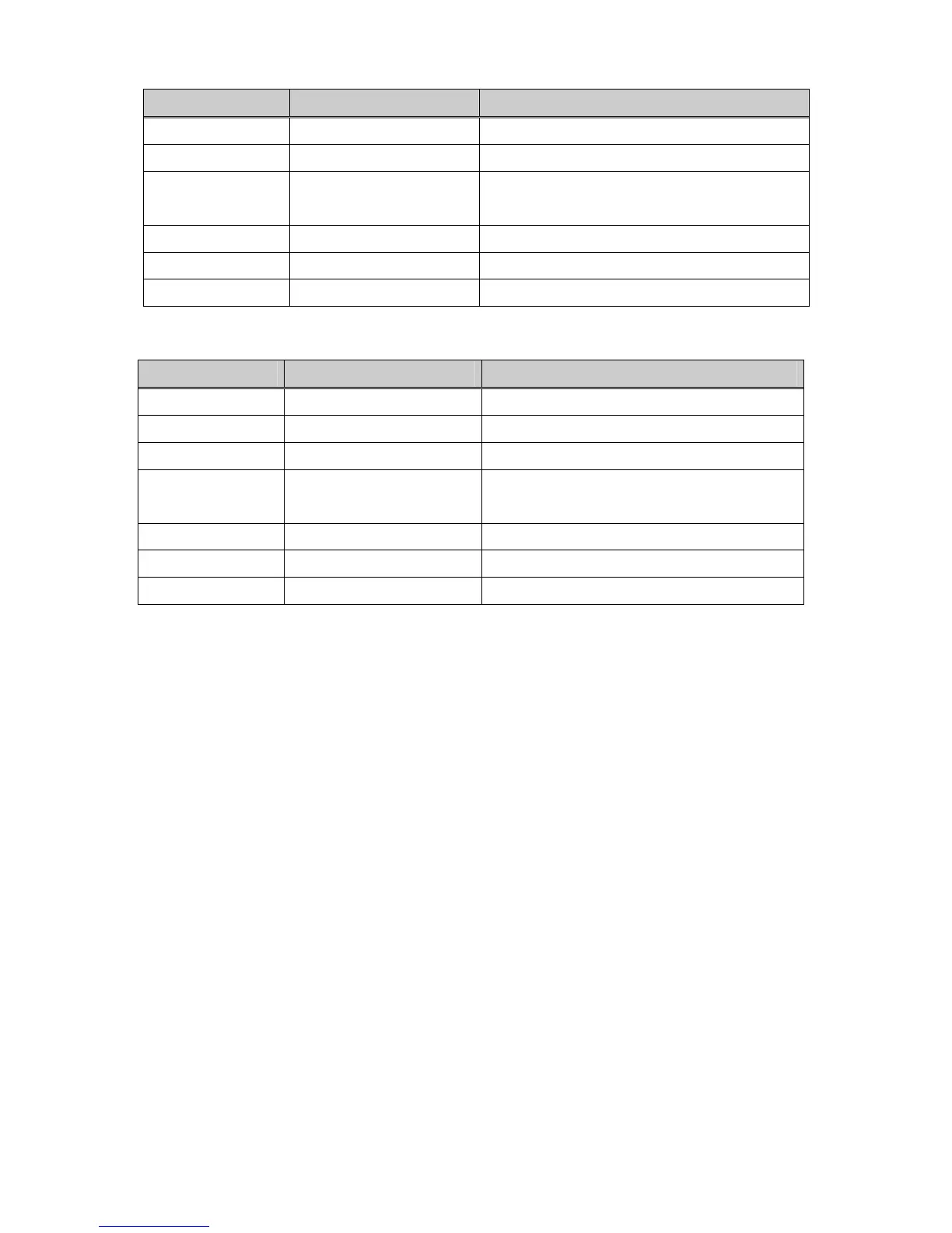
1. SV-iP5A Setting
Parameter code Display Setting Value
< COM-01 > Opt B/D RS485 displayed automatically
< COM-02 > Opt mode Set Commands controlled via communication
< I/O- 90 > Inv. No.
1~250
(Verify the assigned number is not duplicated)
< I/O- 91 > Baud rate 9600 bps (Factory default)
< I/O- 92 > COM Lost Cmd
note3)
User setting
< I/O- 93 > COM Time Out
note3)
1.0 sec (Factory default)
2. SV-iV5 Setting
Parameter code Display Setting Value
< EXT_01 > Opt B/D RS485 displayed automatically
< FUN_01 > Run/Stop Src Option
< FUN_02 > Spd Ref Sel Option
< I/O_95 > Inv Number
1~250
(Verify the assigned number is not duplicated)
< I/O_96 > 485 Baud Rate 9600 bps (Factory default)
< I/O_97 > Lost Command
note3)
User setting
< I/O_98 > Comm. Timer
note3)
1.0 sec (Factory default)
note3)
It is used for Emergency Stop when communication between inverter and Master is not done
properly. It is activated when communication is not done even once for the set time. It indicates the
inverter is not controlled by Remote. Set this value for safety.
⑦ Power down the inverter for the connection of converter when step○
6
is finished.
⑧ If the inverter is to be placed at the end of the network trunk line, install a jumper on the option card
to enable the termination resistor (120 Ω). (See the Figure 3).
4.2.
4.3.
4.3.1.
RS232-485 Converter Installation
The installation of converters depends on the manufacturers. Refer to the converter installation manual for
detailed converter installation.
Connection guide for the communication card, the computer and the
converter
System Configuration