EasyManuals Logo

LS XGT Series User Manual

LS XGT Series
200 pages
To Next Page IconTo Next Page
To Previous Page IconTo Previous Page
Page #31 background imageLoading...
Page #31 background image
Chapter 3 Installation and Test Operation
3-4
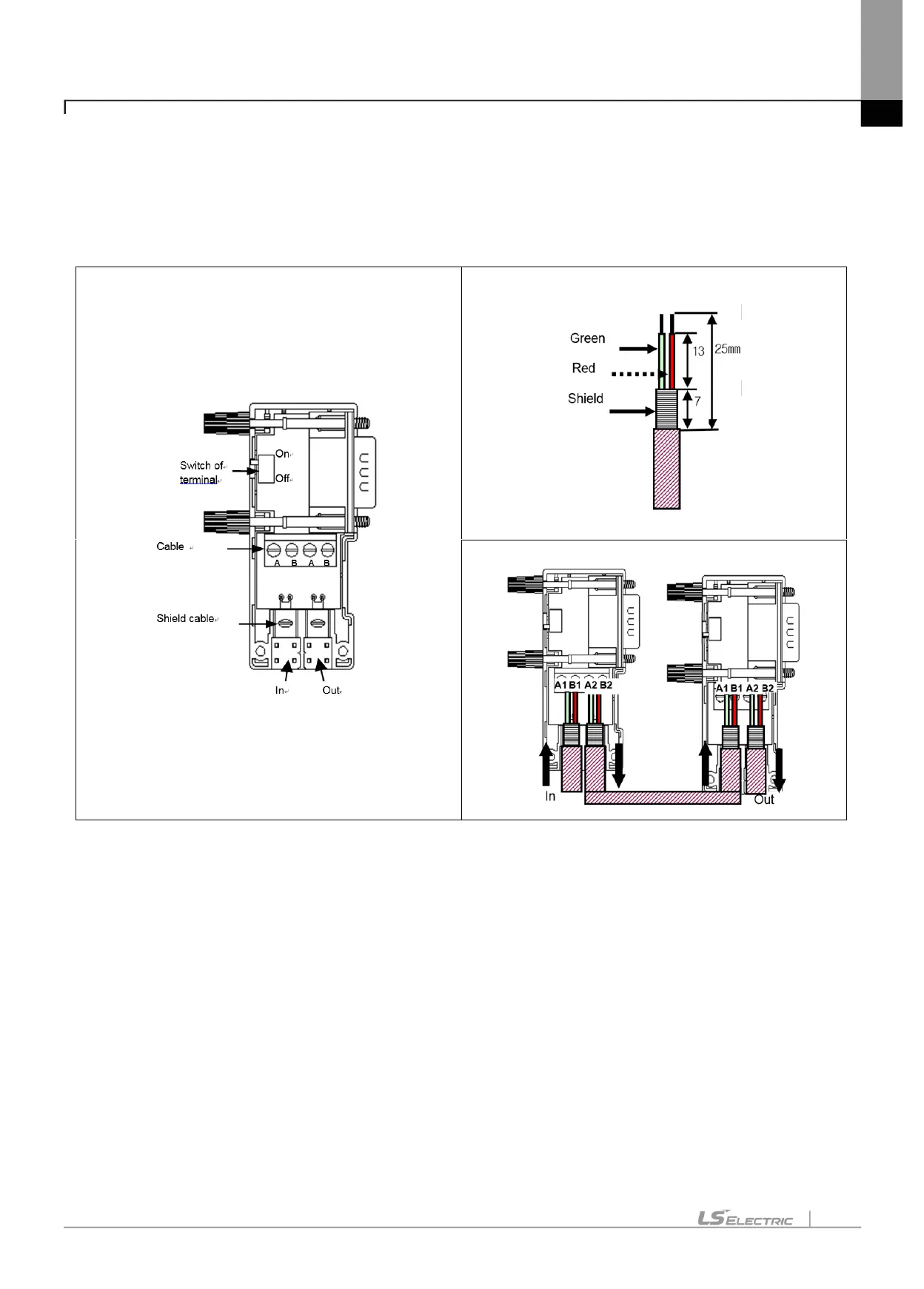
2) Pnet Connector structure and wiring method
(1) Input Line: green line is connected to A1, red line is connected to B1
(2) Output line: green line is connected to A2, red line is connected to B2
(3) Connect shield to clamp of shield
(4) In case of installing the connector at terminal, install the cable at A1, B1
<Connector structure>
<Cable structure>
<Cable wiring method>

Table of Contents

Other manuals for LS XGT Series

Questions and Answers:

Question and Answer IconNeed help?

Do you have a question about the LS XGT Series and is the answer not in the manual?

LS XGT Series Specifications

General IconGeneral
BrandLS
ModelXGT Series
CategoryControl Unit
LanguageEnglish

Related product manuals