Human Machine Interface Installation Guide
XP40-TTA / XP40-TTE
This installation guide provides simple function information of HMI control. Please read
carefully this data sheet and manuals before using products. Especially read safety
precautions and handle the products properly.
■ Meaning of warning and caution inscription
WARNING indicates a potentially hazardous situation which,
if not avoided, could result in death or serious injury
CAUTION indicates a potentially hazardous situation which,
if not avoided, may result in minor or moderate injury.
It may also be used to alert against unsafe practices
① Do not contact the terminals while the power is applied.
② Protect the product from being gone into by foreign metallic matter.
③ Do not manipulate the battery.(Charge, disassemble, hitting, short, soldering)
① Be sure to check the rated voltage and terminal arrangement before wiring.
② When wiring, tighten the screw of terminal block with the specified torque rage.
③ Do not install the flammable things on surroundings.
④ Do not use the HMI in the environment of direct vibration.
⑤ Except expert A/S staff, Do not disassemble or fix or modify the product.
⑥ Use the HMI in an environment that meets the general specifications contained in
this datasheet.
⑦ Be sure that external load does not exceed the rating of output module.
⑧ When disposing of HMI and battery, treat it as industrial waste.
■ To install, observe the below conditions.
10 ~ 85%RH, non-condensing
10 ~ 85%RH, non-condensing
10 times in
each
direction
for
X, Y, Z
■ For system configuration, the following version is necessary.
1) Window CE : V1.07 above
2) XP-Runtime/ XP-Builder : V1.33 above
■ Check the battery attached in the XGT Panel.
1) Use : Back up data, Operating RTC
2) Standard : CR2032
■ Check the mounting Brackets in the box.
1) Bracket Quantity : 2 Set(four for each, eight total)
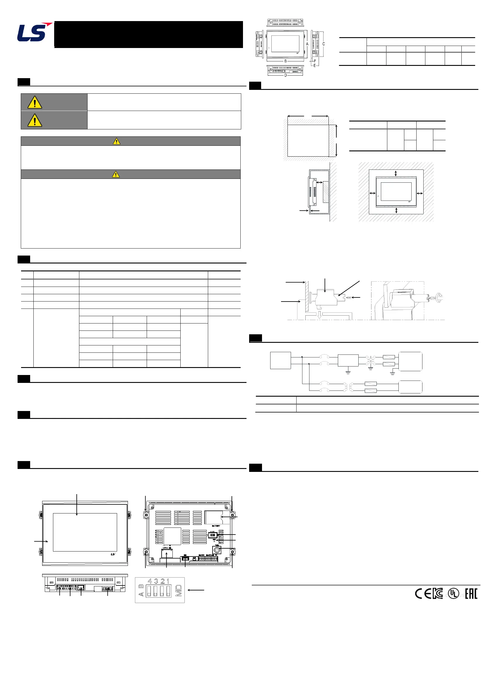
■ This is front part of the XP. Refer to each name when driving the system. For more
information, refer to user manual.
■ When you install the XGT Panel, a panel, designed to mount the XGT Panel inside should
be specified and allowed for.
1) Panel Cut Dimensions (mm)
2) Mounting XGT Panel
① Ensure that there is 100mm clearance around all sides of the panel to be affected
at a minimum by the electromagnetic wave or heat.
② The panel thickness (Z) should be 1.6 ~ 9.5mm.
③ Insert the mounting brackets into the XP insertion slots. Tightening the screws with
too much force can damage the product. (The recommend torque is 0.62Nㆍm)
④ Use screwdriver to tighten brackets screw as illustration shown.
⑤ For more information about affixing brackets and precedures, refer to user manual.
■ Power Wiring
1) In case that the power is out of rated voltage, connect constant voltage transformer.
2) Connect the power having the small noise between cables or between earths.
In case of having lots of noise, connect the insulation transformer or noise filter.
3) Separate the XGT Panel power supply cable from the main circuit cable (high voltage and
current) and input/output cable.
4) Use the third grounding resistance (less than 100Ω) and use cables with a cross sectional
area greater than 2.0 ㎟.
■ Warranty period: 18 months after the production date.
■ Scope of Warranty
18-month warranty is available except:
1) The troubles caused by improper condition, environment or treatment except the
instructions of LSIS.
2) The troubles caused by external devices.
3) The troubles caused by remodeling or repairing based on the user’s own discretion.
4) The troubles caused by improper usage of the product.
5) The troubles caused by the reason which exceeded the expectation from science and
technology level when LSIS manufactured the product.
6) The troubles caused by natural disaster.
■ Change in specifications
Product specifications are subject to change without notice due to continuous product
development and improvement.
LSIS Co., Ltd http://www.lsis.com 10310001246, V4.0 (2015.11)
HEAD OFFICE
Tel: (82) 2-2034-4870 Fax: (82) 2-2034-4888 E-mail: cshwang@lsis.com
LSIS USA Inc._Chicago, U.S.A. Tel: (1) 847-941-8240 Fax: (1) 847-941-8259
LSIS(ME) FZE_Dubai, U.A.E. Tel: (971) 4-886-5360 Fax: (971) 4-886-5361
LSIS_Shanghai, China Tel: (86) 21-5237-9977-8609 Fax: (86) 21-5237-7189
LS-VINA, Hanoi, Vietnam Tel: (84) 4-6275-8055 Fax: (84) 4-3882-0220
LSIS Europe B.V._Netherlands Tel: (31) 20-654-1420 Fax: (31) 20-654-1429
LSIS Tokyo, Japan Tel: (81) 3-6268-8241 Fax: (81) 3-6268-8240
ⓒ LSIS Co., Ltd 2015 All Rights Reserved.
Parts name and Dimension (mm)
10
11
12
13
※
Please set the 4
th
switch On(A) to use termination resistor for RS-422/485
Power
PE
Supply
Noise
Filter
Other Device
HMI Power
 Loading...