6
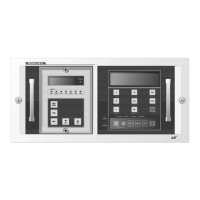
1.1 The External View
1.1 The External View1.1 The External View
1.1 The External View
1. LCD Display 12.
CB ON key (Red LED)
2. Fault Indicator Reset Switch 13.
CB OFF key (Green LED)
3. 16 × 2 LCD 14.
Local key (Yellow LED)
4. Fault Indicator LED • Local output contact
5. Relay Set / Run key • Manual operation of CB ON/OFF
• Transfer from initial menu to
setting menu
15.
Remote key (Yellow LED)
6. ESC key • Remote output contact
• Cancel or
Move to upper menu
• Remote operation of CB ON/OFF
7. Enter key 16.
Clear Key
•
Saving of changed data
/ Clear execution
• Wh / Varh, The number of CB operation,
8. Decrement key CB conducting time, Clear max. Vo (zero)
• Decrease data or
Move between items
17.
CPU Reset Key
9. Increment key 18.
Protection Cover
• Increase data or
Move between items
19.
COMM LED (Red)
10.
Display Select key • Blinking during communication
11.
Function key (Red LED) 20.
POWER LED (Red)
1.
1. 1.
1. The Layout of M
The Layout of MThe Layout of M
The Layout of MMI
MIMI
MI
 Loading...