Name
Description
①
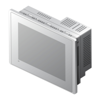
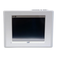
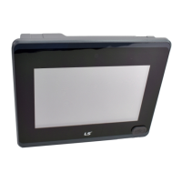
Front view
1) Analog touch panel: User touch input
2) LCD: screen display
②
LED Status
Indicates operation status of module.
Green
Normal RUN status
(monitoring, downloading the project data)
Initializing mode when booting
(HMI does not Ready)
Red
Error occurs
(communication error, project data error)
③
Panel fixed part XGT Panel is fixed at panel by bracket.
④
Power terminal
cover
Prevention from electric shock
⑤
USB interface
1) USB memory connection: logging/recipe/screen data backup
2) USB memory connection: project data transmission/backup
3) User interface connection: use of mouse/keyboard
4) Printer connection: printing is available
⑥
Communication
interface
RS-232C, RS-422/485: For communication with controller (PLC)
⑦
Reset switch Hardware reset switch
⑧
Battery cover Open or close when replacing the battery
⑨
Tool interface
RS-232C interface
1) Project data transmission
2) Logging/recipe/alarm/screen data backup
3) Machine software upgrade
⑩
Setting switch
Module setting switch
No.1 Reserved
No.2
A setting
RS-422/485 Terminal Switch Off (120Ω)
⑪
Power terminal It consists of power input and FG terminal
⑫
Ethernet terminal
Ethernet: 10Base-T / 100Base-TX
1) Project data transmission
2) logging/recipe/alarm/screen data backup
3) machine software upgrade
4) PLC/control machine communication
※
Supported on XP40-TTA


 To Next Page
 Loading...