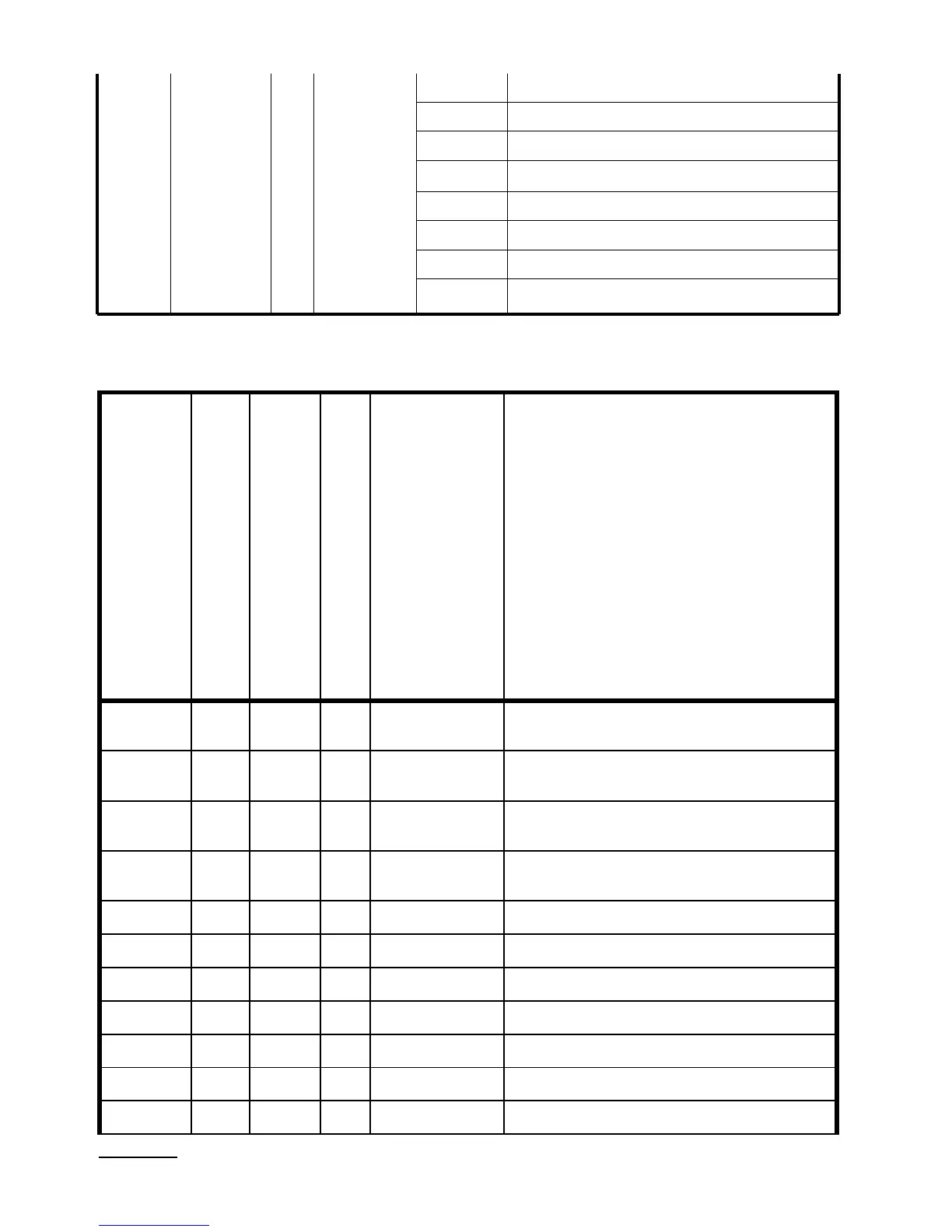
Table 10
Bit 7 LED4 – Signaling of alarm nr 4.
Bit 6 LED3 – Signaling of alarm nr 3.
Bit 5 LED2 – Signaling of alarm nr 2.
Bit 4 LED1 – Signaling of alarm nr 1.
Bit 3 Status of the alarm relay nr 4.
Bit 2 Status of the alarm relay nr 3.
Bit 1 Status of the alarm relay nr 2.
Bit 0 Status of the alarm relay nr 1.
4049 Status2 z/o
The value is placed in two suc-
cessive 16-bit registers. These
registers include the same data as
32-bit registers from the area 7600
The value is placed in 32-bit
registers
Symbol
write
(w)
/
rea-
dout
(r)
Range Description
7200 7600
CoLLo
w/r -19999...99999
Lower threshold of the display colour
change
7202 7601
CoLHI
w/r -19999...99999
Upper threshold of the display colour
change
7204 7602
ovrLo
w/r -19999...99999
Lower threshold of the display
narrowing
7206 7603
ovrHI
w/r -19999...99999
Upper threshold of the display
narrowing
7208 7604
PRL 1
w/r -19999...99999 Lower threshold of alarm 1
7210 7605
PrH 1
w/r -19999...99999 Upper threshold of alarm 1
7212 7606
PRL 2
w/r -19999...99999 Lower threshold of alarm 2
7214 7607
PrH 2
w/r -19999...99999 Upper threshold of alarm 2
7216 7608
PRL 3
w/r -19999...99999 Lower threshold of alarm 3
7218 7609
PrH 3
w/r -19999...99999 Upper threshold of alarm 3
7220 7610
PRL 4
w/r -19999...99999 Lower threshold of alarm 4
 Loading...